 Yamaha Tracer MT09TRA - Service manual > Clutch


Removing the clutch
1. Remove:
- Cover "1"
- Clutch cover "2"
- Gasket
TIP
Loosen each bolt 1/4 of a turn at a time, in stages and in a crisscross pattern.
After all of the bolts are fully loosened, remove them.

2. Remove:
- Oil pump driven sprocket "1" Refer to "OIL PUMP"
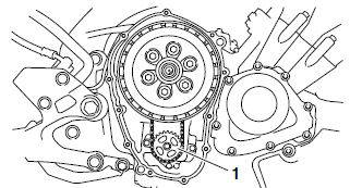
3. Remove:
- Compression spring bolts "1"
- Compression springs
- Pressure plate "2"
- Pull rod "3"

4. Remove:
- Friction plates 1 "1"
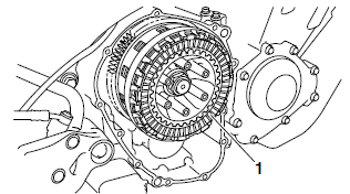
5. Remove:
- Clutch plates "1"
- Friction plates 2
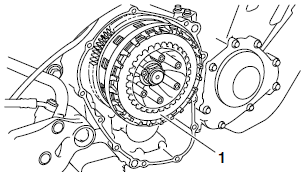
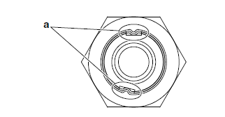
6. Straighten the clutch boss nut rib "a".
7. Loosen:
- Clutch boss nut "1"
TIP
While holding the clutch boss "2" with the universal clutch holder "3", loosen the clutch boss nut.
 Universal clutch holder
90890-04086
Universal clutch holder YM-91042

8. Remove:
- Clutch boss nut
- Conical spring washer
- Washer
- Clutch boss
- Thrust plate
- Clutch housing
- Oil pump drive chain
Checking the friction plates
The following procedure applies to all of the friction plates.
1. Check:
- Friction plate 1, 2 Damage/wear → Replace the friction plates as a set.
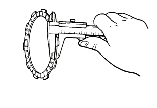
2. Measure:
- Friction plate 1, 2 thickness Out of specification → Replace the friction plates as a set.
TIP
Measure the friction plate at four places.
 Friction plate 1
thickness 2.92-3.08 mm (0.115-0.121 in)
Wear limit 2.82 mm (0.111 in)
Friction plate 2 thickness 2.92-3.08 mm (0.115-0.121 in)
Wear limit 2.82 mm (0.111 in)
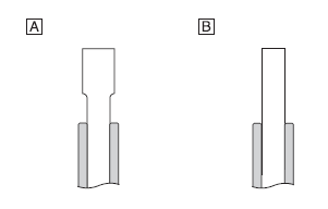
A. Friction plate 1
B. Friction plate 2
Checking the clutch plates
The following procedure applies to all of the clutch plates.
1. Check:
- Clutch plate
Damage → Replace the clutch plates as a set.
2. Measure:
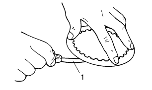
- Clutch plate warpage (with a surface plate and thickness gauge "1") Out of specification → Replace the clutch plates as a set.
 Thickness gauge
90890-03180
Feeler gauge set YU-26900-9
 Clutch plate thickness
1.90-2.10 mm (0.075-0.083 in)
Warpage limit 0.10 mm (0.004 in)
Checking the clutch springs
The following procedure applies to all of the clutch springs.
1. Check:
- Clutch spring
Damage → Replace the clutch springs as a set.
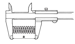
2. Measure:
- Clutch spring free length "a".
Out of specification → Replace the clutch springs as a set.
 Clutch spring free
length 52.50 mm (2.07 in) Limit 49.88 mm (1.96 in)
Checking the clutch housing
1. Check:
- Clutch housing dogs.
Damage/pitting/wear → Deburr the clutch housing dogs or replace the clutch housing.
TIP
Pitting on the clutch housing dogs will cause erratic clutch operation.
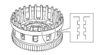
2. Check:
- Oil pump drive sprocket "1" Cracks/damage/wear → Replace.
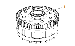
3. Check:
- Bearing.
Damage/wear → Replace the bearing and clutch housing.
Checking the clutch boss
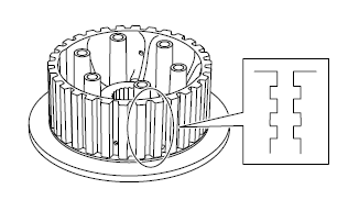
1. Check:
Clutch boss splines. Damage/pitting/wear → Replace the clutch boss.
TIP
Pitting on the clutch boss splines will cause erratic clutch operation.
Checking the pressure plate
1. Check:
- Pressure plate "1".
Cracks/damage → Replace.
- Bearing "2".
Damage/wear → Replace.

Checking the primary drive gear
1. Check:
- Primary drive gear
Damage/wear → Replace the crankshaft and clutch housing as a set.
Excessive noise during operation → Replace the crankshaft and clutch housing as a set.
Checking the primary driven gear
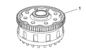
1. Check:
- Primary driven gear "1".
Damage/wear → Replace the clutch housing and crankshaft as a set.
Excessive noise during operation → Replace the clutch housing and crankshaft as a set.
Checking the pull lever shaft and pull rod
1. Check:
- Pull lever shaft pinion gear teeth "1"
- Pull rod teeth "2"
Damage/wear → Replace the pull rod and pull lever shaft as a set.
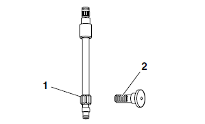
2. Check:
- Pull rod bearing.
Damage/wear → Replace.
Installing the clutch
1. Install:
- Oil pump drive chain "1"
- Clutch housing "2"
TIP
Install the oil pump drive chain onto the oil pump drive sprocket "a".

2. Install:
- Thrust plate
- Clutch boss "1"
- Washer
- Conical spring washer "2"
- Clutch boss nut "3"

 Clutch boss nut 125 Nm
(12.5 m*kgf, 90 ft*lbf) LOCTITE
TIP
- Install the conical spring washer on the main axle with the "OUT" mark "a" facing away from the vehicle.
- While holding the clutch boss "1" with the universal clutch holder "4", tighten the clutch boss nut
- Stake the clutch boss nut at cutouts "b" in the main axle.
 Universal clutch holder
90890-04086
Universal clutch holder YM-91042

3. Install:
- Friction plates 1
- Clutch plates
- Friction plates 2
TIP
- First, install a friction plate and then alternate between a clutch plate and a friction plate.
- Install the last friction plate "1" offset from the other friction plates "2", making sure to align a projection on the friction plate with the punch mark "a" on the clutch housing.

4. Install:
- Bearing (into the pressure plate)
- Pull rod "1"
- Pressure plate "2"
- Clutch springs
- Clutch spring bolts "3"
 Clutch spring bolt 10
Nm (1.0 m*kgf, 7.2 ft*lbf)
- Oil pump driven sprocket "4"
 Oil pump driven
sprocket bolt 15 Nm (1.5 m*kgf, 11 ft*lbf) LOCTITE
TIP
- Tighten the clutch spring bolts in stages and in a crisscross pattern.
- Apply lithium-soap-based grease onto the pull rod.
- Position the pull rod so that the teeth "a" face towards the hole "b". Then, install the clutch cover.

5. Install:
- Dowel pins
- Clutch cover gasket

- Clutch cover
- Cover
 Clutch cover bolt 12 Nm
(1.2 m*kgf, 8.7 ft*lbf)
TIP
- Apply engine oil onto the bearing.
- Tighten the clutch cover bolts in stages and in a crisscross pattern.
6. Install:
- Pull lever
TIP
- Install the pull lever with the "O" mark facing toward lower side.
- When installing the pull lever, push the pull lever and check that the punch mark "a" on the pull lever aligns with the mark "b" on the clutch cover. Make sure that the pull rod teeth and pull lever shaft pinion gear are engaged.

7. Adjust:
- Clutch lever free play Refer to "ADJUSTING THE CLUTCH LEVER FREE PLAY"
 Clutch lever free play
10.0-15.0 mm (0.39-0.59 in)
See also:
 Yamaha Tracer MT09TRA - Service manual > Shift shaft
Checking the shift shaft 1. Check: Shift shaft "1" Bends/damage/wear → Replace. Shift shaft spring "2" Collar

 BMW G310GS
 Honda CBR125RW
 Husqvarna 401 Vitpilen
 KTM 890 Duke R
 Mash Dirt Track 650
 Peugeot Kisbee
 Yamaha Tracer MT-09
 Honda CBR125RW
 Peugeot Kisbee
 Yamaha Tracer MT-09