 Honda CBR125RW - Service manual > Ignition System
SYSTEM LOCATION
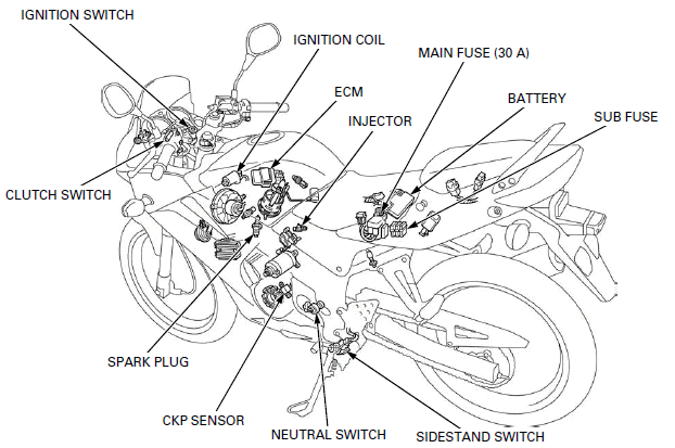
- CLUTCH SWITCH
- IGNITION SWITCH
- IGNITION COIL
- ECM
- INJECTOR
- MAIN FUSE (30 A)
- BATTERY
- SUB FUSE
- SIDESTAND SWITCH
- NEUTRAL SWITCH
- CKP SENSOR
- SPARK PLUG
SYSTEM DIAGRAM
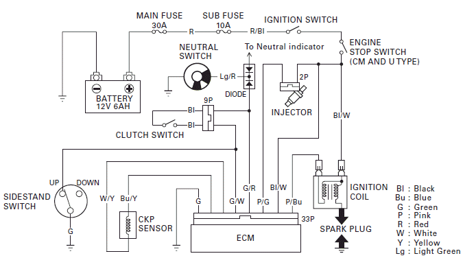
SERVICE INFORMATION
GENERAL

- The ECM may be damaged if dropped. Also if the connector is disconnected when current is flowing, the excessive voltage may damage the module. Always turn off the ignition switch before servicing.
- Use spark plug of the correct heat range. Using a spark plug with an incorrect heat range can damage the engine.
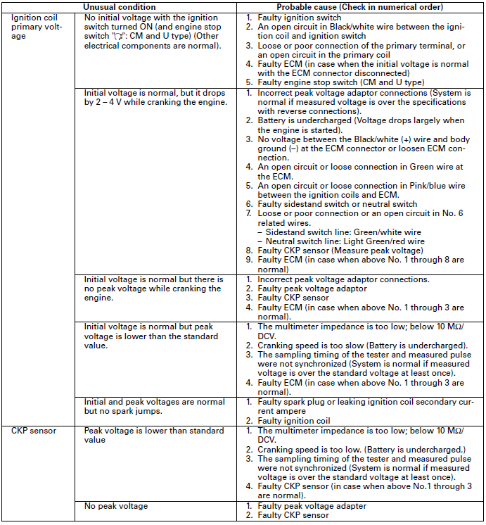
- When servicing the ignition system, always follow the steps in the troubleshooting table.
- The transistorized ignition system uses an electrically controlled ignition timing system. No adjustments can be made to the ignition timing.
- Some electrical components may be damaged if terminals or connectors are connected or disconnected while the ignition switch is ON position and current is present.
- A faulty ignition system is often related to poorly connected or corroded connections. Check those connections before proceeding.
- The ECM varies ignition timing according to the engine speed. The TP sensor signals the ECM to compensate the ignition timing according to the throttle opening.
- Make sure the battery is adequately charged. Using the starter motor with a weak battery results in a slower engine cranking speed as well as no spark at the spark plug.
- Refer to following components information's:
- Diode
- Ignition switch
- Engine stop switch (CM and U type)
- Neutral switch
- Sidestand switch
- Clutch switch
SPECIFICATIONS

TORQUE VALUE
Timing hole cap 6.0 N-m (0.6 kgf-m, 4.4 lbf-ft)
TOOLS
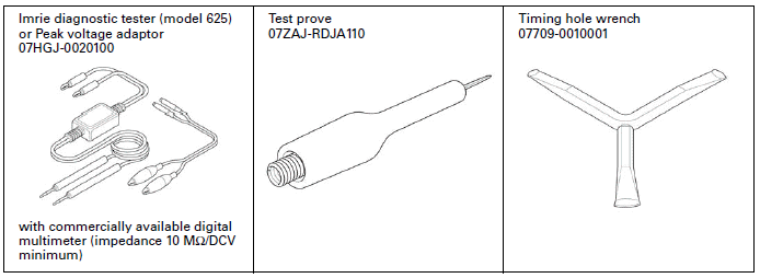
TROUBLESHOOTING
- Inspect the following before diagnosing the system.
- Faulty spark plug
- Loose spark plug cap or spark plug wire connection
- Water got into the spark plug cap (Leaking the ignition coil secondary voltage)
- If there is no spark at cylinder, temporarily exchange the ignition coil with a known-good one and perform the spark test. If there is spark, the original ignition coil is faulty.
- "Initial voltage" of the ignition primary coil is the battery voltage
with the ignition switch turned ON (and engine stop switch "
 ":
CM and U type) (The engine is not cranked by the starter motor).
No spark at spark plug
IGNITION SYSTEM INSPECTION
NOTE:
- If there is no spark at the plug, check all connections for loose or poor contact before measuring the peak voltage.
- Use a commercially available digital multimeter with an impedance of 10 MΩ/DCV minimum.
- The display value differs depending upon the internal impedance of the multimeter.
- If using the Imrie diagnostic tester (model 625), follow the manufacturer's instructions.
Connect the peak voltage adaptor to the digital multimeter, or use the Imrie diagnostic tester.
TOOL: Imrie diagnostic tester (model 625) or Peak voltage adaptor 07HGJ-0020100 with commercially available digital multimeter (impedance 10 MΩ/DCV minimum)

IGNITION COIL PRIMARY PEAK VOLTAGE
NOTE:
- Check all system connections before performing this inspection. Loose connectors can cause incorrect readings.
- If the system is disconnected, incorrect peak voltage might be measured.
- Check the cylinder compression and check that the spark plug is installed correctly in the cylinder head.
Shift the transmission into neutral and disconnect the spark plug cap.
Connect a known good spark plug to the spark plug cap and ground it to the cylinder head as done in a spark test.
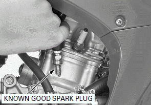
Lift and support the fuel tank.
Open the rubber sheet.
Do not disconnect the ignition coil primary wire.
With the ignition coil primary wire connected, connect the peak voltage adaptor or Imrie tester to the ignition coil primary terminal and ground.
TOOL: Imrie diagnostic tester (model 625) or
Peak voltage adaptor 07HGJ-0020100 with commercially available digital
multimeter (impedance 10 MΩ/DCV minimum)
CONNECTION: Pink/blue (+) - Ground (-)
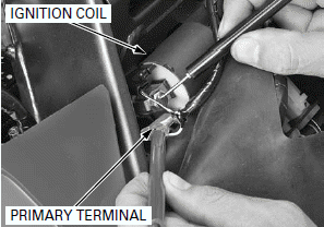
Shift the transmission into neutral.
Turn the ignition switch ON (and engine stop switch " ":
CM and U type).
Avoid touching the spark plug and tester probes to prevent electric shock.
Crank the engine with the starter motor with the throttle grip fully opened and read ignition coil primary peak voltage.
PEAK VOLTAGE: 100 V minimum
If the peak voltage is abnormal, follow the checks described in the troubleshooting table.
Close the rubber sheet.
Remove the suitable support and close the fuel tank.
CKP SENSOR PEAK VOLTAGE
NOTE:
Check the cylinder compression and check that the spark plug is installed correctly in the cylinder head.
Remove the ECM.
Connect the peak voltage tester or adaptor probes to the ECM 33P connector terminals of the wire harness side.
TOOLS:
Imrie diagnostic tester (model 625) or
Peak voltage adaptor 07HGJ-0020100 with commercially available digital
multimeter (impedance 10 MΩ/DCV minimum)
Test probe 07ZAJ-RDJA110
CONNECTION: Blue/yellow (+) - White/yellow (-)
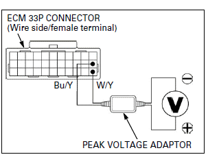
Shift the transmission into neutral.
Turn the ignition switch ON.
Crank the engine with the starter motor with the throttle grip fully opened and read CKP sensor peak voltage.
PEAK VOLTAGE: 0.7 V minimum
If the peak voltage measured at the ECM 33P connector is abnormal, measure the peak voltage at the CKP sensor connector.
Turn the ignition switch OFF.
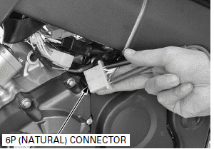
Disconnect the alternator/CKP sensor 6P (Natural) connector and connect the tester probes to the connector terminals of the CKP sensor side.
CONNECTION: Blue/yellow (+) - White/yellow (-)
In the same manner as at the ECM 33P connector, measure the peak voltage and compare it to the voltage measured at the ECM 33P connector.
NOTE:
- If the peak voltage measured at the ECM is abnormal and the one measured at the CKP sensor is normal, the wire harness has an open or short circuit or loose connection.
- If the peak voltage of the CKP sensor side is lower than standard value, follow the checks described in the troubleshooting table.
Install the removed parts in the reverse order of removal.
IGNITION TIMING
Warm up the engine.
Stop the engine and remove the timing hole cap using a special tool.
TOOL: Timing cap wrench 07709-0010001 or equivalent
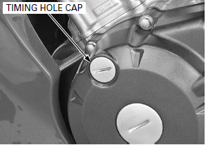
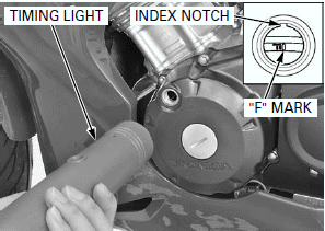
Read the instructions for timing light operation.
Connect the timing light to the spark plug wire.
Start the engine and let it idle.
IDLE SPEED: 1,450 +- 100 min-1 (rpm)
The ignition timing is correct if the "F" mark on the flywheel aligns with the index notch on the left crankcase cover.
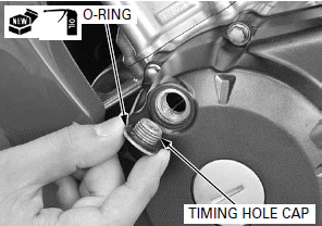
Apply engine oil to a new O-ring and install it to the timing hole cap.
Install and tighten the timing hole cap to the specified torque.
TORQUE: 6.0 N-m (0.6 kgf-m, 4.4 lbf-ft)
IGNITION COIL
REMOVAL/INSTALLATION
Lift and support the fuel tank.
Remove the ECM.
Disconnect the spark plug cap.
Disconnect the wire connectors from the ignition coil.
Remove the bolts and ignition coil.
Route the wire properly.
Install the removed parts in the reverse order of removal.

See also:
 Honda CBR125RW - Service manual > Battery/Charging System
SYSTEM LOCATION REGULATOR/RECTIFIER ALTERNATOR BATTERY MAIN FUSE (30A)
 Honda CBR125RW - Service manual > Electric Starter
SYSTEM LOCATION IGNITION SWITCH CLUTCH SWITCH STARTER SWITCH STARTER RELAY SWITCH DIODE MAIN FUSE (30 A) BATTERY STARTER MOTOR NEUTRAL SWITCH SIDESTAND SWITCH SUB FUSE

 BMW G310GS
 Honda CBR125RW
 Husqvarna 401 Vitpilen
 KTM 890 Duke R
 Mash Dirt Track 650
 Peugeot Kisbee
 Yamaha Tracer MT-09
 Honda CBR125RW
 Peugeot Kisbee
 Yamaha Tracer MT-09