 Honda CBR125RW - Service manual > Lights/Meters/Switches
SYSTEM LOCATION
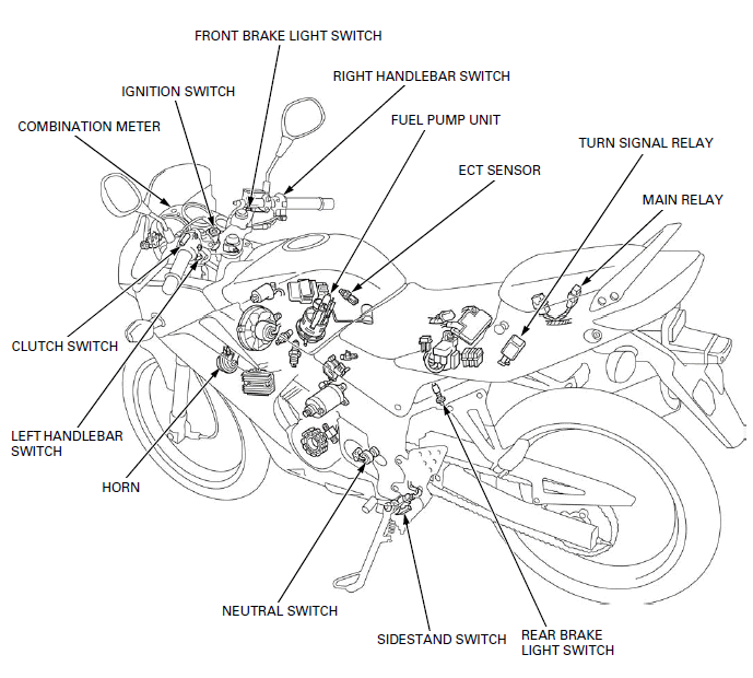
- CLUTCH SWITCH
- COMBINATION METER
- IGNITION SWITCH
- FRONT BRAKE LIGHT SWITCH
- RIGHT HANDLEBAR SWITCH
- FUEL PUMP UNIT
- ECT SENSOR
- TURN SIGNAL RELAY
- MAIN RELAY
- REAR BRAKE LIGHT SWITCH
- SIDESTAND SWITCH
- NEUTRAL SWITCH
- HORN
- LEFT HANDLEBAR SWITCH
SERVICE INFORMATION
GENERAL

- Note the following when replacing the halogen headlight bulb.
- Wear clean gloves while replacing the bulb. Do not put fingerprints on the headlight bulb, as they may create hot spots on the bulb and cause it to fail.
- If you touch the bulb with your bare hands, clean it with a cloth moistened with alcohol to prevent its early failure.
- Be sure to install the dust cover after replacing the headlight bulb.
- A halogen headlight bulb becomes very hot while the headlight is ON, and
remains hot for a while after it is turned OFF.
Be sure to let it cool down before servicing.
- Check the battery condition before performing any inspection that requires proper battery voltage.
- A continuity test can be made with the switches installed on the motorcycle.
- The following color codes are used throughout this section.
Bu = Blue
G = Green
Lg = Light Green
R = Red
Bl = Black
Gr = Gray
O = Orange
W = White
Br = Brown
Lb = Light Blue
P = Pink
Y = Yellow
SPECIFICATIONS
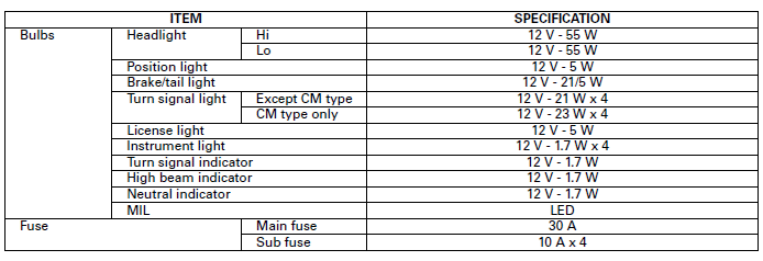
TORQUE VALUES
Turn signal light lens screw 0.9 N-m (0.1 kgf-m, 0.7 lbf-ft)
Turn signal light mounting nut 8.8 N-m (0.9 kgf-m, 6.5 lbf-ft)
License light cover screw 1.0 N-m (0.1 kgf-m, 0.7 lbf-ft)
License light mounting nut 4.5 N-m (0.5 kgf-m, 3.3 lbf-ft)
HEADLIGHT
BULB REPLACEMENT
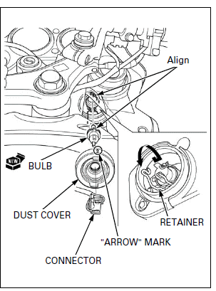
Disconnect the headlight bulb connector.
Remove the dust cover.
Unhook the bulb retainer and remove the headlight bulb.
Remove the headlight bulb.

Avoid touching halogen headlight bulb. Finger prints can create hot spots that cause a bulb to break.
Install a new bulb, while aligning the tabs of the bulb with the slots of the headlight unit.
Hook the bulb retainer into the headlight unit groove.
Install the dust cover with the "arrow" mark facing up.
Connect the headlight connector.
REMOVAL/INSTALLATION
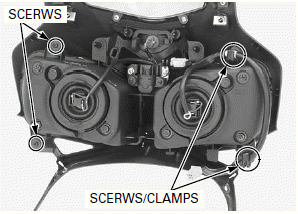
Remove the upper cowl.
Remove the headlight mounting screws, clamps and headlight unit.
Route the wires properly.
Install the headlight unit, headlight mounting screws and clamps.
Install the upper cowl.
POSITION LIGHT
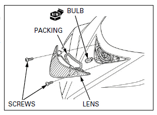
BULB REPLACEMENT
Remove the screws and position light lens.
Remove the bulb from the socket, replace it with a new one.
Check the packing is installed in position and is in good condition, replace it with a new one if necessary.
Install the position light lens and screws.
Tighten the screws.
TURN SIGNAL LIGHTS
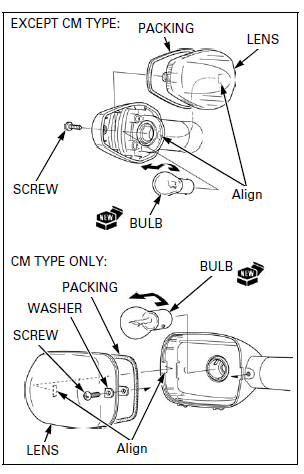
BULB REPLACEMENT
Remove the screw, washer (CM type only), turn signal light lens.
While pushing in the bulb, turn it counterclockwise to remove it.
Replace the bulb with a new one.
Check the packing is installed in position and is in good condition, replace it with a new one if necessary.
Install the turn signal light lens by aligning the slot with the tab of the turn signal light.
Install the screw and washer (CM type only).
Tighten the screw to the specified torque.
TORQUE: 0.9 N-m (0.1 kgf-m, 0.7 lbf-ft)
REMOVAL/INSTALLATION
FRONT
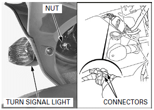
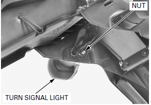
Disconnect the turn signal light connectors.
Remove the turn signal light mounting nut and turn signal light.
Route the wire properly.
Install the turn signal light and turn signal light mounting nut.
Tighten the nut to the specified torque.
TORQUE: 8.8 N-m (0.9 kgf-m, 6.5 lbf-ft)
Connect the turn signal light connectors.
REAR
Remove the following:
- Rear cowl
- Brake/tail light
Disconnect the turn signal light connectors.
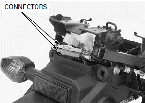
Remove the turn signal light mounting nut and turn signal light.
Route the wire properly
Install the turn signal light in the reverse order of removal.
TORQUE: Turn signal light mounting nut: 8.8 N-m (0.9 kgf-m, 6.5 lbf-ft)
BRAKE/TAIL LIGHT
BULB REPLACEMENT
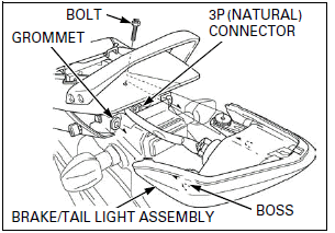
Remove the pillion seat.
Remove the bolt.
Release the brake/tail light assembly bosses from the rear fender grommets.
Disconnect the brake/tail light 3P (Natural) connector and remove the brake/tail light.
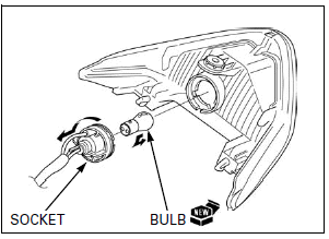
Turn the bulb socket counterclockwise and remove it.
While pushing in the bulb, turn it counterclockwise to remove it.
Replace the bulb with a new one.
Install the removed parts in the reverse order of removal.
LICENSE LIGHT
BULB REPLACEMENT
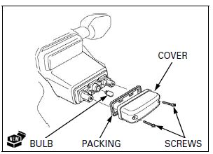
Remove the screws and license light cover.
Remove the bulb from the socket, replace it with a new one.
Check the packing is installed in position and is in good condition, replace it with a new one if necessary.
Install the license light cover and screws.
Tighten the screws to the specified torque.
TORQUE: 1.0 N-m (0.1 kgf-m, 0.7 lbf-ft)
REMOVAL/INSTALLATION
Remove the following:
- Rear cowl
- Brake/tail light
- Rear turn signal light
Remove the bolts and rear turn signal light stay.
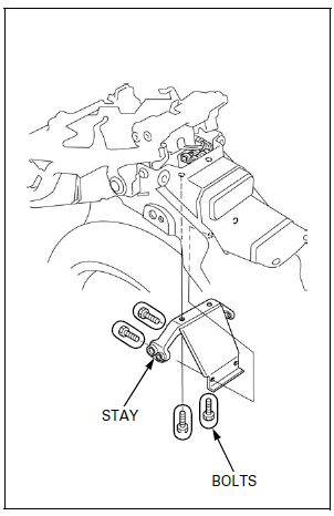
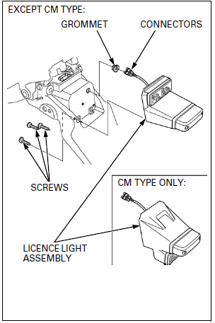
Disconnect the license light wire connectors.
Remove the screws.
Pull out the wire from the rear fender and remove the license light assembly and grommet.
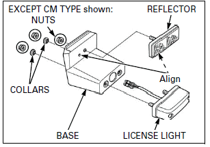
Remove the nuts, collars, reflector and license light from the license light base.
Install the reflector by aligning the pin with hole.
Install and tighten the nut.
Install the removed parts in the reverse order of removal.
TORQUE: License light mounting nut: 4.5 N-m (0.5 kgf-m, 3.3 lbf-ft)
COMBINATION METER
BULB REPLACEMENT
Remove the combination meter assembly.
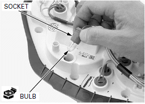
Remove the meter bulb sockets.
Remove the bulb from the socket, replace it with a new one.
Install the removed parts in the reverse order of removal.
REMOVAL/INSTALLATION
Remove the inner cowl.
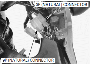
Disconnect the combination meter 9P (Natural) and 3P (Natural) connectors.
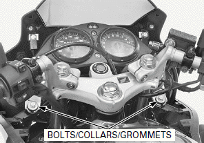
Remove the bolts, collars and grommets.
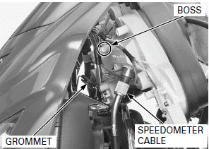
Lift the combination meter assembly while releasing the boss from the grommet.
Disconnect the speedometer cable from the combination meter assembly.
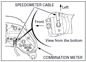
Install the combination meter assembly in the reverse order of removal.
NOTE:
When connecting the speedometer cable, note the cable direction as shown.
DISASSEMBLY/ASSEMBLY
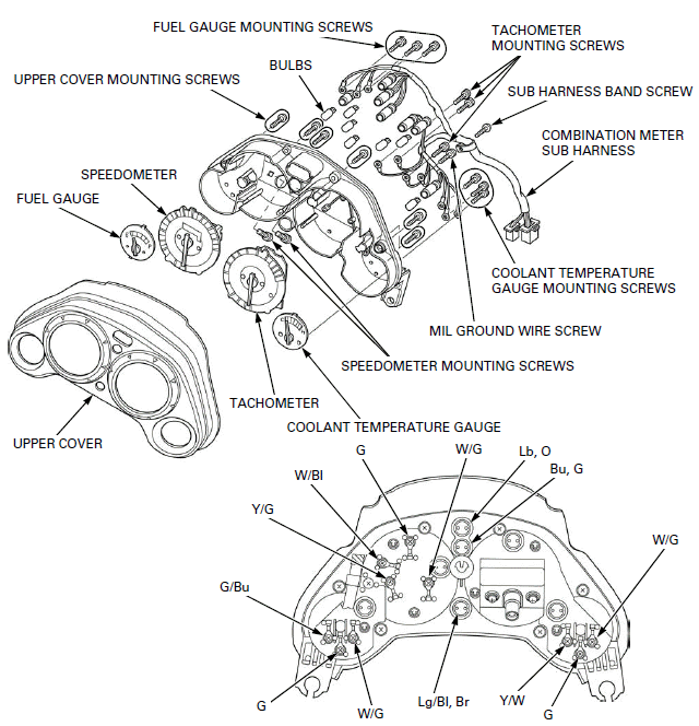
Remove the combination meter assembly.
Remove the following:
- Upper cover mounting screws and upper cover
- Coolant temperature gauge mounting screws and coolant temperature gauge
- Tachometer mounting screws and tachometer
- MIL ground wire screw
- Speedometer mounting screws and speedometer
- Fuel gauge mounting screws and fuel gauge
- Sub harness band screw
- Bulb sockets and combination meter sub harness
Assemble the combination meter in the reverse order of disassembly.
TACHOMETER
INSPECTION
Remove the combination meter assembly.
Temporarily connect the combination meter 9P (Natural) and 3P (Natural) connectors.
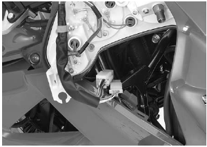
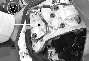
Start the engine and measure the voltage between the Yellow/green (+) and Green (-) wire terminals.
There should be at least 6 V pulse voltage.
If there is pulse voltage, replace the tachometer.
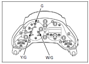
If there is no pulse voltage, check for following:
- Open or short circuit in Yellow/green wire
- Open or short circuit in White/green line
- Blown main fuse
- Blown sub fuse
- Faulty main relay
- Open circuit in Green wire
If the wires and tachometer are normal, replace the ECM.
COOLANT TEMPERATURE GAUGE/ ECT SENSOR
GAUGE INSPECTION
Lift and support the fuel tank.
The coolant temperature is too high, but the gauge needle does not moves
Disconnect the ECT sensor 3P connector.
Ground the ECT sensor 3P connector Green/blue terminal at the wire harness side.
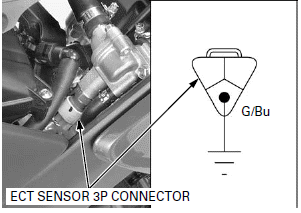
Turn the ignition switch ON and check the coolant temperature gauge needle.
If the gauge needle moves, check the ECT sensor.
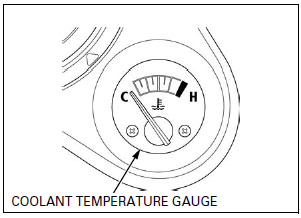
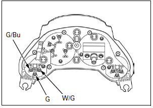
If the gauge needle does not moves, check for following:
- Open or short circuit in Yellow/green wire
- Open or short circuit in White/green line
- Blown main fuse
- Blown sub fuse
- Faulty main relay
- Open circuit in Green wire
If the wires and ECT sensor are normal, replace the coolant temperature gauge.
The coolant temperature is low, but the gauge needle moves
Turn the ignition switch OFF.
Disconnect the ECT sensor 3P connector.
Turn the ignition switch ON.
If the gauge needle moves, inspect the ECT sensor.
If the gauge needle does not move, check for a short circuit in the Green/blue wire. If the wire is OK, replace the coolant temperature gauge.
ECT SENSOR INSPECTION
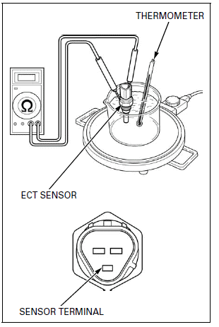
Remove the ECT sensor.
Wear insulated gloves and adequate eye protection.
Keep flammable materials away from the burner.
Heat the coolant (1:1 mixture) with an electric heating element.
Suspend the ECT sensor in heated coolant and check the continuity through the sensor as the coolant heats up.
NOTE:
- Soak the ECT sensor in coolant up to its threads with at least 40 mm (1.6 in) from the bottom of the pan to the bottom of the ECT sensor.
- Keep temperature constant for 3 minutes before testing. A sudden change of temperature will result in incorrect readings. Do not let the thermometer or ECT sensor touch the pan.

Replace the ECT senor if it is out of specification by more than 10% at any temperature listed.
Install the ECT sensor.
IGNITION SWITCH
INSPECTION
Lift and support the fuel tank.
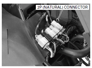
Open the rubber sheet.
Disconnect the ignition switch 2P (Natural) connector.
Check for continuity between the switch side connector terminals in each switch position.
Continuity should exist between the color coded wires as shown in the table. 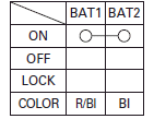
Close the rubber sheet.
Remove the suitable support and close the fuel tank.
REMOVAL/INSTALLATION
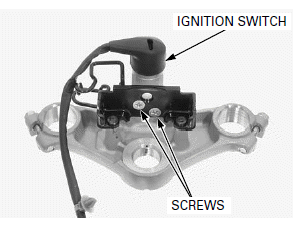
Remove the top bridge.
Remove the ignition switch mounting screws and ignition switch.
Install the ignition switch onto the top bridge.
Install and tighten the ignition switch mounting screws securely.
Install the top bridge in the reverse order of removal.
HANDLEBAR SWITCHES
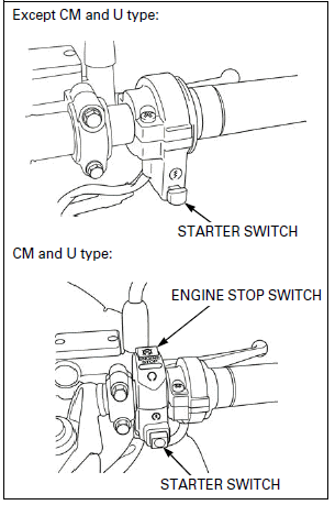
RIGHT HANDLEBAR SWITCH
Lift and support the fuel tank.
Open the rubber sheet.
Disconnect the right handlebar switch 6P (Natural) connector.
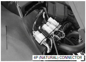
Check for continuity between the switch side connector terminals in each switch position.
Continuity should exist between the color coded wire as shown in the tables.
STARTER SWITCH: 
ENGINE STOP SWITCH: (CM and U type) 
Close the rubber sheet.
Remove the suitable support and close the fuel tank.
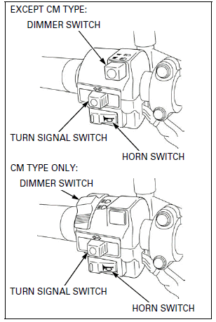
LEFT HANDLEBAR SWITCHS
Lift and support the fuel tank.
Open the rubber sheet.
Disconnect the left handlebar switch 9P (Natural) and 2P (Black) connectors.
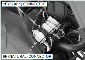
Check for continuity between the switch side connector terminals in each switch position.
Continuity should exist between the color coded wire as shown in the tables.
DIMMER SWITCH: 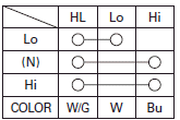
TURN SIGNAL SWITCH: 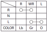
HORN SWITCH: 
Close the rubber sheet.
Remove the suitable support and close the fuel tank.
BRAKE LIGHT SWITCHES
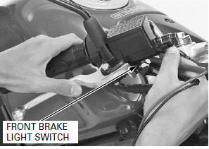
FRONT
Disconnect the front brake light switch connectors and check for continuity between the switch terminals.
There should be continuity with the brake lever squeezed, and no continuity with the brake lever released.
REAR
Remove the rear cowl.
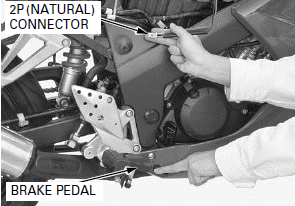
Disconnect the rear brake light switch 2P (Natural) connector.
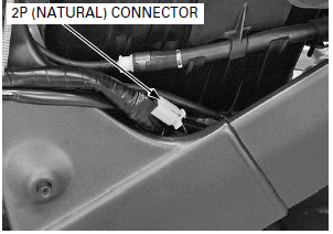
Check for continuity between the switch side connector terminals.
There should be continuity with the brake pedal depressed, and no continuity when the brake pedal released.
NEUTRAL SWITCH
INSPECTION
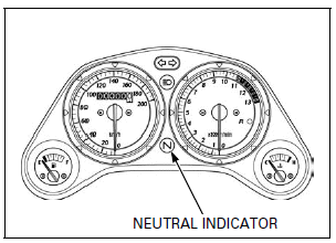
Make sure that the neutral indicator come on with the ignition switch ON and transmission is in neutral.
If the neutral indicator does not come on, inspect as follows:
Disconnect the neutral switch wire connector.
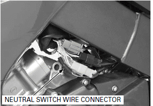
Check for continuity between the switch side Light green/red terminal and ground.
There should be continuity with the transmission is in neutral, and no continuity when the transmission is into gear.
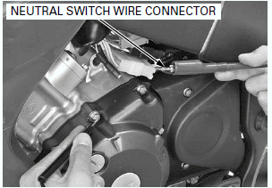
REMOVAL
Disconnect the neutral switch wire connector.
Remove the drive sprocket cover.
Remove the neutral switch mounting bolt.
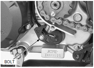
Remove the neutral switch and O-ring.
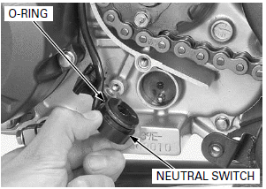
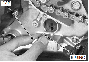
Remove the spring cap and spring from the shift drum.
INSTALLATION
Check the spring cap for wear or damage, replace if necessary.
NOTE:
Bend the spring cap by force or crush the contact point will cause poor electricity connection.
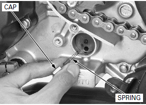
Install the spring into the spring cap and install them into the shift drum.
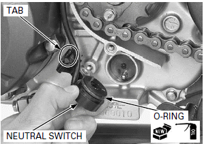
Apply engine oil to a new O-ring and install it to the neutral switch.
Route the wire properly.
Install the neutral switch.
Route the wire properly.
Install and tighten the neutral switch mounting bolt.
Install the drive sprocket cover.
Connect the neutral switch wire connector.
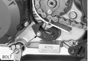
SIDESTAND SWITCH
INSPECTION
Disconnect the sidestand switch 3P (Green) connector.
Check for continuity between the switch side connector terminals.
There should be continuity with the sidestand retracted and no continuity with the sidestand lowered.
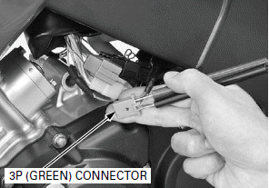
REMOVAL/INSTALLATION
Disconnect the sidestand switch 3P (Green) connector.
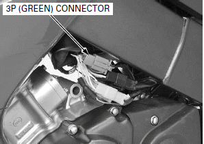
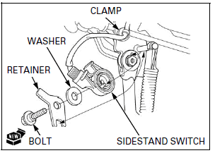
Remove the bolt, retainer, washer and sidestand switch.
Release the wire harness clamp.
Install the sidestand switch, washer, retainer and new bolt.
Tighten the bolt securely.
Install the wire harness clamp.
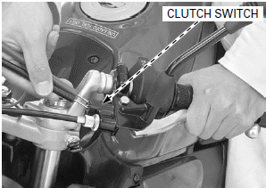
CLUTCH SWITCH
Disconnect the clutch switch wire connectors and check for continuity between the switch terminals.
There should be continuity with the clutch lever squeezed and no continuity with the clutch lever released.
FUEL GAUGE/FUEL LEVEL SENSOR
INSPECTION
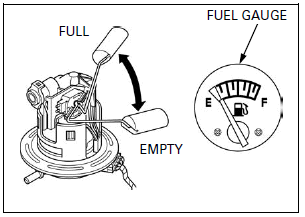
FUEL GAUGE
Remove the fuel pump unit.
Connect the fuel pump unit 5P connector.
Turn the ignition switch ON.
Move the float from empty to full, then check the fuel gauge needle.
If the needle does not move, check for following:
- Open or short circuit in Yellow/green wire
- Open or short circuit in White/green line
- Blown main fuse
- Blown sub fuse
- Faulty main relay
- Open circuit in Green wire
If the wires are normal, inspect the fuel level sensor.
If the fuel level sensor is normal, replace the fuel gauge with a new one.
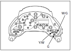
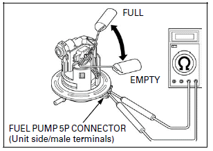
FUEL LEVEL SENSOR
Remove the fuel pump unit.
Connect the ohmmeter to the fuel pump unit 5P connector Yellow/white and Green terminals.
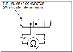
Inspect the resistance of the float at the full and empty positions.

Replace the fuel pump unit assembly if fuel level sensor is out of specification.
Install the fuel pump unit.
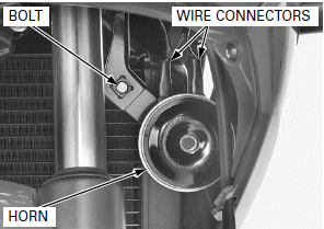
HORN
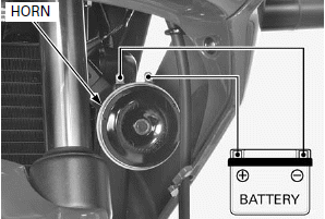
INSPECTION
Disconnect the connectors from the horn.
Connect a 12 V battery to the horn terminals.
The horn is normal if it sounds when the 12 V battery is connected across the horn terminals.
INSPECTION
Disconnect the connectors from the horn.
Connect a 12 V battery to the horn terminals.
The horn is normal if it sounds when the 12 V battery is connected across the horn terminals.
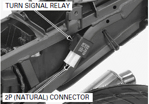
TURN SIGNAL RELAY
INSPECTION
1. Recommended Inspection
Check the following:
- Battery condition
- Burned out bulb or non-specified wattage
- Blown sub fuse
- Ignition switch and turn signal switch function
- Loose connector
Are the above items in good condition?
NO - Replace or repair the malfunction part (s).
YES - GO TO STEP 2.
2. Turn Signal Circuit Inspection
Remove the rear cowl.
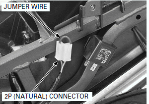
Disconnect the turn signal relay 2P (Natural) connector from the relay.
Short the Brown and Gray terminals of the turn signal relay connector with a jumper wire.
Start the engine and check the turn signal light by moving the turn signal switch all the way in the right side or left side.
Is the light come on?
YES -
- Faulty turn signal relay
- Poor connection of the connector
NO - Open circuit in the wire harness
REMOVAL/INSTALLATION
Remove the rear cowl.
Disconnect the turn signal relay 2P (Natural) connector from the relay.
Remove the turn signal relay from the frame.
Install the turn signal relay in the reverse order of removal.
MAIN RELAY
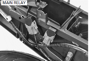
Remove the rear cowl.
Remove the main relay.
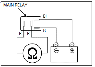
Connect an ohmmeter to the main relay connector terminals.
CONNECTION: Red - Red
Connect a 12 V battery to the following main relay connector terminals.
CONNECTION: Green - Black
There should be continuity only when 12 V battery is connected.
If there is no continuity only when the 12 V battery is connected, replace the main relay.
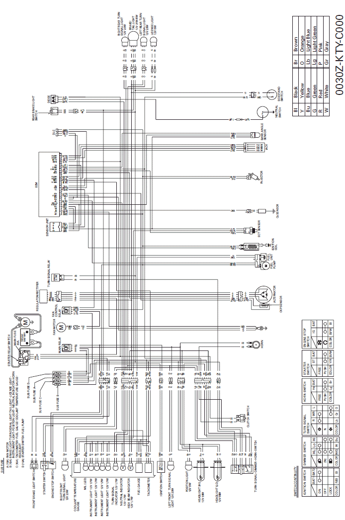
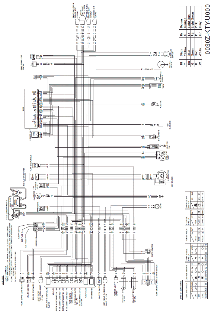
Wiring Diagrams
ED, E, F, II G type:
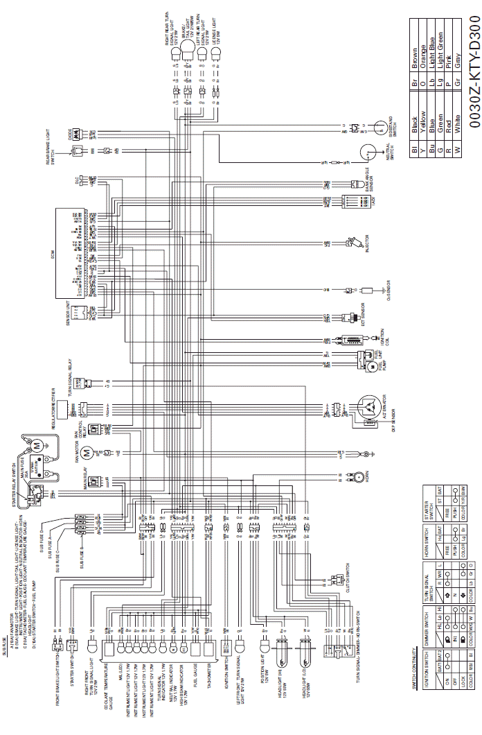
CM type:
U type:
See also:
 Honda CBR125RW - Service manual > Electric Starter
SYSTEM LOCATION IGNITION SWITCH CLUTCH SWITCH STARTER SWITCH STARTER RELAY SWITCH DIODE MAIN FUSE (30 A) BATTERY STARTER MOTOR NEUTRAL SWITCH SIDESTAND SWITCH SUB FUSE
 Honda CBR125RW - Service manual > Troubleshooting
ENGINE DOES NOT START OR IS HARD TO START 1. Spark Plug Inspection Remove and inspect spark plug. Is the spark plug in good condition?

 BMW G310GS
 Honda CBR125RW
 Husqvarna 401 Vitpilen
 KTM 890 Duke R
 Mash Dirt Track 650
 Peugeot Kisbee
 Yamaha Tracer MT-09
 Honda CBR125RW
 Peugeot Kisbee
 Yamaha Tracer MT-09