 Yamaha Tracer MT09TRA - Service manual > Electrical system
Electrical parts handling
NOTICE
Never disconnect a battery lead while the engine is running; otherwise, the electrical components could be damaged.
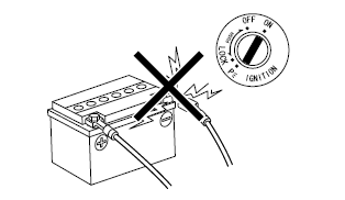
NOTICE
When disconnecting the battery leads from the battery, be sure to disconnect the negative battery lead first, then the positive battery lead. If the positive battery lead is disconnected first and a tool or similar item contacts the vehicle, a spark could be generated, which is extremely dangerous.
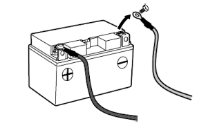
TIP
If a battery lead is difficult to disconnect due to rust on the battery terminal, remove the rust using hot water.
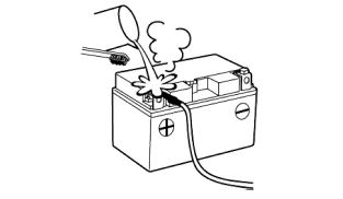
NOTICE
Be sure to connect the battery leads to the correct battery terminals. Reversing the battery lead connections could damage the electrical components.
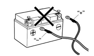
NOTICE
When connecting the battery leads to the battery, be sure to connect the positive battery lead first, then the negative battery lead.
If the negative battery lead is connected first and a tool or similar item contacts the vehicle while the positive battery lead is being connected, a spark could be generated, which is extremely dangerous.

NOTICE
Turn the main switch to "OFF" before disconnecting or connecting an electrical component.

NOTICE
Handle electrical components with special care, and do not subject them to strong shocks.
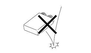
NOTICE
Electrical components are very sensitive to and can be damaged by static electricity.
Therefore, never touch the terminals and be sure to keep the contacts clean.
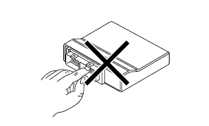
TIP
When resetting the ECU by turning the main switch to "OFF", be sure to wait approximately 5 seconds before turning the main switch back to "ON".

Checking the electrical system
TIP
Before checking the electrical system, make sure that the battery voltage is at least 12 V.

NOTICE
Never insert the tester probes into the coupler terminal slots. Always insert the probes from the opposite end "a" of the coupler, taking care not to loosen or damage the leads.
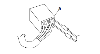
NOTICE
For waterproof couplers, never insert the tester probes directly into the coupler. When performing any checks using a waterproof coupler, use the specified test harness or a suitable commercially available test harness.
Checking the connections
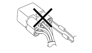
Check the leads, couplers, and connectors for stains, rust, moisture, etc.
1. Disconnect:
- Lead
- Coupler
- Connector
NOTICE
- When disconnecting a coupler, release the coupler lock, hold both sections of the coupler securely, and then disconnect the coupler.
- There are many types of coupler locks; therefore, be sure to check the type of coupler lock before disconnecting the coupler.
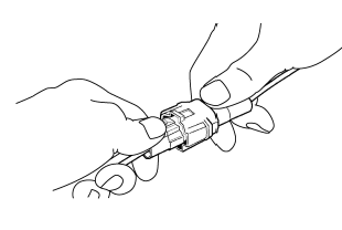
NOTICE
When disconnecting a connector, do not pull the leads. Hold both sections of the connector securely, and then disconnect the connector.

2. Check:
- Lead
- Coupler
- Connector
Moisture  Dry with an air blower.
Rust/stains  Connect and disconnect
several times.

3. Connect:
- Lead
- Coupler
- Connector
TIP
- When connecting a coupler or connector, push both sections of the coupler or connector together until they are connected securely.
- Make sure all connections are tight.
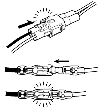
4. Check:
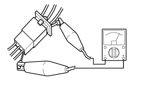
- Continuity (with the pocket tester)
 Pocket tester 90890-03112
Analog pocket tester YU-03112-C
TIP
- If there is no continuity, clean the terminals.
- When checking the wire harness, perform steps (1) to (3).
- As a quick remedy, use a contact revitalizer available at most part stores.

5. Check:
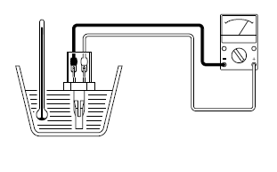
- Resistance
 Pocket tester 90890-03112
Analog pocket tester YU-03112-C
TIP
The resistance values shown were obtained at the standard measuring temperature of 20 ºC (68 ºF). If the measuring temperature is not 20 ºC (68 ºF), the specified measuring conditions will be shown.
 Intake air temperature
sensor resistance 5.40-6.60 k
 at 0
ºC (32 ºF) 290-390
  at 80 ºC (176
ºF)
Special tools
The following special tools are necessary for complete and accurate tune-up and assembly. Use only the appropriate special tools as this will help prevent damage caused by the use of inappropriate tools or improvised techniques. Special tools, part numbers or both may differ depending on the country.
When placing an order, refer to the list provided below to avoid any mistakes.
TIP
- For U.S.A. and Canada, use part number starting with "YM-", "YU-", or "ACC-".
- For others, use part number starting with "90890-".


See also:
 Yamaha Tracer MT09TRA - Service manual > Quick fasteners
Rivet type 1. Remove: Quick fastener TIP To remove the quick fastener, push its pin with a screwdriver, then pull the fastener out.
 Yamaha Tracer MT09TRA - Service manual > Specifications
General specifications Engine specifications

 BMW G310GS
 Honda CBR125RW
 Husqvarna 401 Vitpilen
 KTM 890 Duke R
 Mash Dirt Track 650
 Peugeot Kisbee
 Yamaha Tracer MT-09
 Honda CBR125RW
 Peugeot Kisbee
 Yamaha Tracer MT-09