 Honda CBR125RW - Service manual > Front Wheel
REMOVAL
Support the motorcycle using a safety stand or hoist, raise the front wheel off the ground.
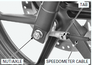
Disconnect the speedometer cable while pushing the tab of the cable.
Remove the axle nut.
Do not operate the brake lever after removing the front wheel.
Remove the axle and front wheel.
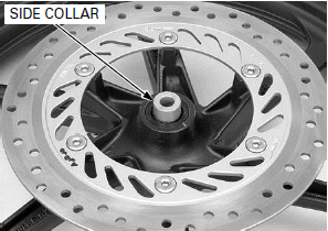
Remove the side collar.
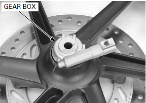
Remove the speedometer gear box.
INSPECTION
AXLE
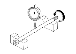
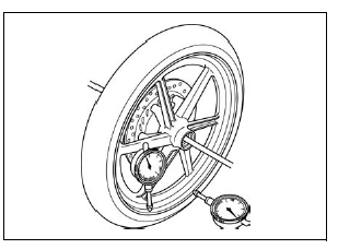
Place the axle on V-blocks.
Turn the axle and measure the runout using a dial indicator.
Actual runout is 1/2 of the total indicator reading.
SERVICE LIMIT: 0.2 mm (0.01 in)
WHEEL RIM
Check the wheel rim runout by placing the wheel in a truing stand.
Spin the wheel by hand and measure the runout using a dial indicator.
Actual runout is 1/2 of the total indicator reading.
SERVICE LIMITS:
Radial: 2.0 mm (0.08 in)
Axial: 2.0 mm (0.08 in)
WHEEL BEARING
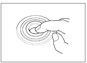
Turn the inner race of each bearing with your finger.
The bearings should turn smoothly and quietly.
Also check that the outer race fits tightly in the wheel hub.
Replace the bearings in pairs.
Remove and discard the bearings if the races do not turn smoothly, quietly, or if they fit loosely in the wheel hub.
WHEEL BALANCE
NOTE:
- Carefully check balance before installing the wheel.
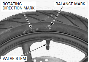
- Mount the tire with the arrow mark facing in the direction of rotation.
- The wheel balance must be checked when the tire is remounted.
- For optimum balance, the tire balance mark (light mass point: a paint dot on the side wall) must be located next to the valve stem. Remount the tire if necessary.
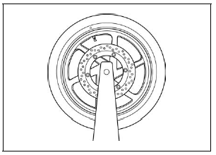
Mount the wheel, tire and brake disc assembly on an inspection stand.
Spin the wheel, allow it to stop, and mark the lowest (heaviest) part of the wheel with chalk.
Do this 2 or 3 times to verify the heaviest area.
If the wheel is balanced, it will not stop consistently in the same position.
To balance the wheel, install a new balance weight on the lightest side of the rim, on the side opposite the chalk marks. Add just enough weight so the wheel will no longer stop in the same position when it is spun.
Do not add more than 60 g to the wheel.
DISASSEMBLY
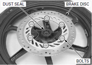
Remove the dust seal from the right wheel hub.
Loosen the brake disc mounting bolts in a crisscross pattern in 2 or 3 steps, and remove the bolts and brake disc.
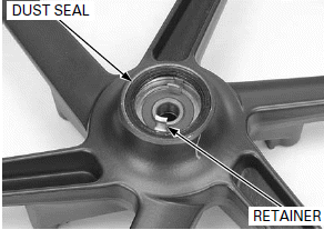
Remove the dust seal and speedometer retainer from the left wheel hub.
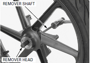
Install the bearing remover head into the bearing.
From the opposite side, install the bearing remover shaft and drive out the bearing from the wheel hub.
Remove the distance collar and drive out the other bearing.
TOOLS:
Bearing remover head, 12 mm 07746-0050300
Bearing remover shaft 07746-0050100
ASSEMBLY
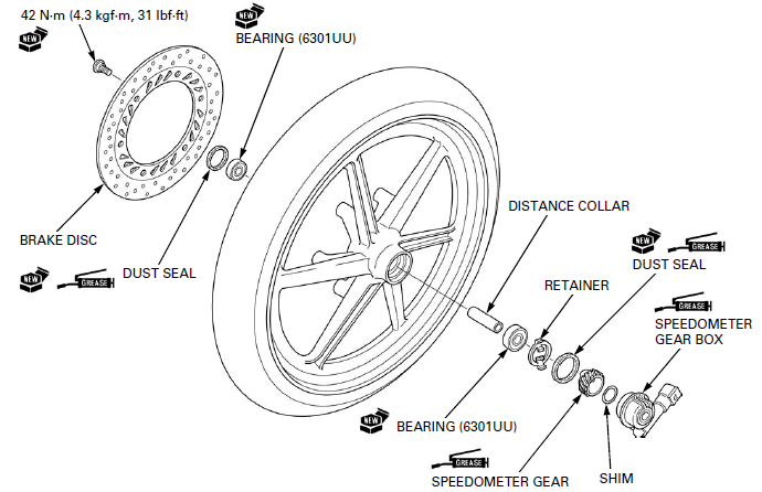
Never install the old bearing, once the bearing has been removed, the bearing must be replaced with new ones.
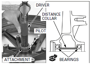
Drive in a new right side bearing squarely with its marked side facing up until it is fully seated.
Install the distance collar.
Drive in a new left side bearing squarely with its marked side facing up until it is seated on the distance collar.
TOOLS:
Driver 07749-0010000
Attachment, 37 x 40 mm 07746-0010200
Pilot, 12 mm 07746-0040200
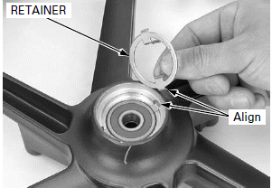
Install the speedometer retainer to the left wheel hub, while aligning the tabs on the retainer with the slots on the hub.
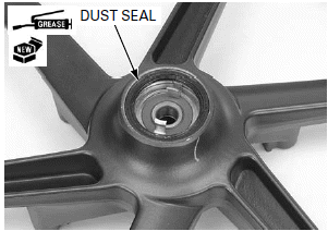
Apply grease to a new dust seal lips.
Install the dust seal until it is fully seated to the left wheel hub.
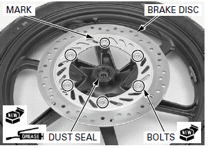
Install the brake disc with the stamped mark "MIN.TH. 3.5 mm" facing outside.
Install and tighten new brake disc bolts to the specified torque in a crisscross pattern in 2 or 3 steps.
TORQUE: 42 N-m (4.3 kgf-m, 31 lbf-ft)
Do not get grease on the brake disc or stopping power will be reduced.
Apply grease to a new dust seal lips.
Install the dust seal until it is flush with the wheel hub surface to the right wheel hub.
INSTALLATION
Apply grease to the speedometer gear teeth, gear inner surface and shaft outer surface.
Install the speedometer gear box into the left wheel hub while aligning the tabs with the slots.
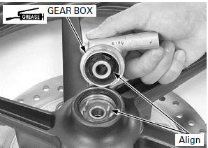
Install the side collar into the right wheel hub.
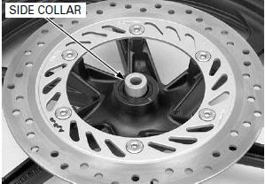
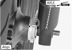
When installing the front wheel, align the following:
- Brake disc between the brake pads
- Speedometer gear box groove with the boss on the left fork leg
NOTE:
Be careful not to damage the brake pads.
Apply a thin coat of grease to the axle rolling surface.
Install the axle from right side.
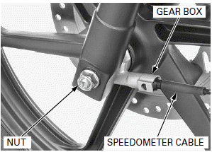
Install and tighten the axle nut to the specified torque.
TORQUE: 59 N-m (6.0 kgf-m, 44 lbf-ft)
Connect the speedometer cable to the speedometer gear box by aligning the tab of the cable with the hole of the gear box.
See also:
 Honda CBR125RW - Service manual > Handlebars
REMOVAL Remove the rearview mirrors. Hold the handlebar weight and remove the screw, then remove both handlebar weights.
 Honda CBR125RW - Service manual > Fork
REMOVAL Remove the following: Front fender Front wheel Do not suspend the brake caliper/ bracket assembly from the brake hose. Do not twist the brake hose.

 BMW G310GS
 Honda CBR125RW
 Husqvarna 401 Vitpilen
 KTM 890 Duke R
 Mash Dirt Track 650
 Peugeot Kisbee
 Yamaha Tracer MT-09
 Honda CBR125RW
 Peugeot Kisbee
 Yamaha Tracer MT-09