 Honda CBR125RW - Service manual > Fork
REMOVAL
Remove the following:
- Front fender
- Front wheel
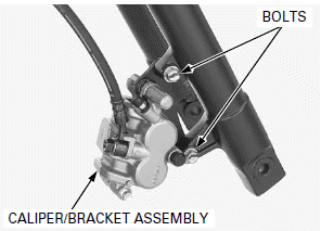
Do not suspend the brake caliper/ bracket assembly from the brake hose. Do not twist the brake hose.
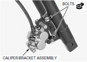
Remove the brake caliper mounting bolts and brake caliper/bracket assembly.
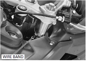
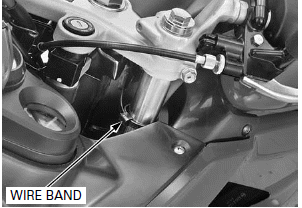
LEFT SIDE: Remove the wire band from the fork pipe.
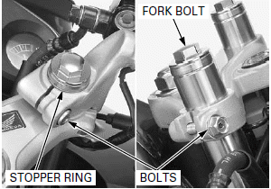
Remove the stopper rings from both fork pipes.
Loosen the handlebar pinch bolts and remove the handlebars.
When the fork is ready to be disassembled, loosen the fork bolt.
Loosen the top bridge pinch bolts.
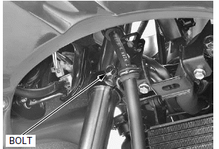
Hold the fork leg and loosen the bottom bridge pinch bolt and lower the fork leg, then remove it.
DISASSEMBLY
Remove the following:
- Fork bolt
- O-ring
- Spring collar
- Spring seat
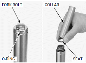
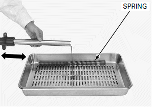
Remove the fork spring.
Drain the fork fluid by pumping the fork pipe several times.
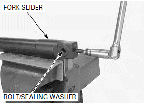
Do not over-tighten the vise on the fork slider.
Set the fork slider in a vise with a piece of wood or soft jaws to avoid damage.
If the fork piston turns with the socket bolt, temporarily install the fork spring, spring seat, spring collar and fork cap.
Remove the fork socket bolt and sealing washer.
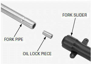
Remove the fork pipe and oil lock piece from the fork slider.
Do not remove the piston ring unless it is to replace with a new one.
Remove the fork piston and rebound spring from the fork pipe.
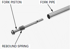
Be careful not to scratch the fork pipe.
Remove the dust seal and stopper ring.
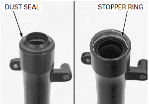
Be careful not to damage the fork slider.
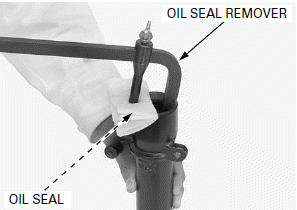
Remove the oil seal using a special tool.
TOOL: Oil seal remover 07748-0010001 or equivalent commercially available
INSPECTION
FORK SPRING
Check the fork spring for fatigue or damage.
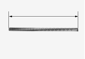
Measure the fork spring free length.
SERVICE LIMIT: 404.1 mm (15.91 in)
FORK PIPE/SLIDER/PISTON
Check the fork pipe, slider and for score marks, scratches, or excessive or abnormal wear.
Check the slider bushing for wear or damage.
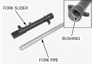
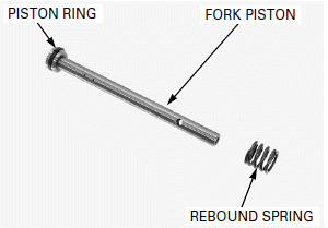
Check the fork piston and piston ring for wear or damage.
Check the rebound spring for fatigue or damage.
Replace any components that are worn or damage.
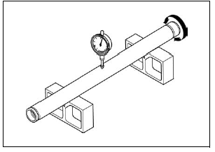
Place the fork pipe on V-blocks.
Turn the fork pipe and measure the runout using a dial indicator.
Actual runout is 1/2 of the total indicator reading
SERVICE LIMIT: 0.20 mm (0.008 in)
ASSEMBLY
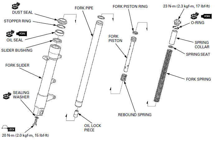
Before assembly, wash all parts with a high flash or non-flammable solvent and wipe them dry.
Apply fork fluid to a new oil seal lips, then install it into the fork slider with its marking facing up.
Drive in the oil seal into the fork slider until the stopper ring groove is visible, using the special to
TOOLS:
Driver 07749-0010000
Attachment, 42 x 47 mm 07746-0010300
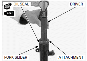
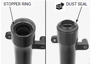
Install the stopper ring into the groove of the fork slider securely.
Install a new dust seal.
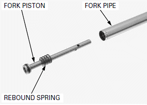
Install the rebound spring to the fork piston and install them into the fork pipe.
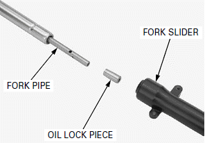
Install the oil lock piece onto the fork piston end.
Install the fork pipe into the fork slider.
Do not over-tighten the vise on the fork slider.
Set the fork slider in a vise with a piece of wood or soft jaws to avoid damage.
Install a new sealing washer to the fork socket bolt.
Apply locking agent to the fork socket bolt threads and install it.
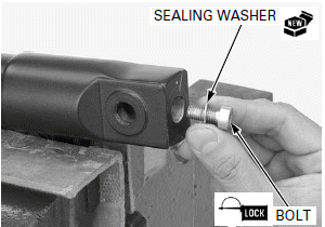
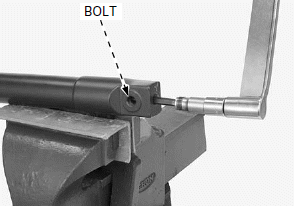
If the fork piston turns with the socket bolt, temporarily install the fork spring, spring seat, spring collar and fork bolt.
Tighten the fork socket bolt to the specified torque.
TORQUE: 20 N-m (2.0 kgf-m, 15 lbf-ft)
Pour the specified amount of recommended fork fluid into the fork pipe.
RECOMMENDED FORK FLUID (Except CM type): Honda ULTRA CUSHION OIL 10W or equivalent
RECOMMENDED FORK FLUID (CM type only): Pro Honda Suspension Fluid SS-8 (10W) or equivalent
FORK FLUID CAPACITY: 206 +- 2.5 cm2 (7.0 +- 0.08 US oz, 7.3 +- 0.09 Imp oz)
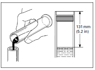
Slowly pump the fork pipe several times to remove any trapped air from the lower portion of the fork pipe.
Compress the fork pipe fully and measure the fluid level from the top of the fork pipe.
FLUID LEVEL: 131 mm (5.2 in)
Pull the fork pipe up and install the fork spring with the tightly wound coil side facing down.
Install the spring seat and spring collar.
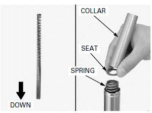
Apply fork fluid to a new O-ring and install it onto the fork bolt.
Tighten the fork bolt after installing the fork pipe into the fork bridges.
Loosely install the fork bolt by pushing it to the fork pipe.
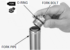
INSTALLATION
Route the wires and cables properly
Install the fork leg through the bottom bridge and top bridge so that the height from the top bridge upper surface to the fork pipe end is 32 mm (1.3 in).
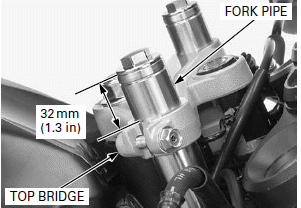
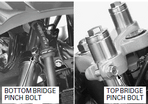
Tighten the bottom bridge and top bridge pinch bolts to the specified torque.
TORQUE:
Bottom bridge pinch bolt: 27 N-m (2.8 kgf-m, 20 lbf-ft)
Top bridge pinch bolt: 23 N-m (2.3 kgf-m, 17 lbf-ft)
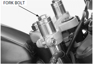
If the fork bolt is loosened, tighten the fork bolt to the specified torque.
TORQUE: 23 N-m (2.3 kgf-m, 17 lbf-ft)
Install the handlebars to both fork pipes while aligning the bosses on the handlebars with the cut outs on the top bridge.
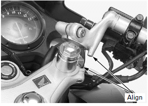
Tighten both handlebar pinch bolts to the specified torque.
TORQUE: 27 N-m (2.8 kgf-m, 20 lbf-ft)
Install the stopper rings to the grooves of both fork pipes.
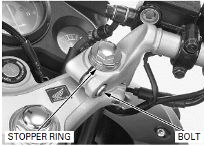
LEFT SIDE: Install the wire band to the fork pipe.
NOTE:
Route the wire properly.
Install the brake caliper/bracket assembly and tighten new brake caliper mounting bolts to the specified torque.
TORQUE: 30 N-m (3.1 kgf-m, 22 lbf-ft)
Install the following:
- Front wheel
- Front fender
See also:
 Honda CBR125RW - Service manual > Front Wheel
REMOVAL Support the motorcycle using a safety stand or hoist, raise the front wheel off the ground. Disconnect the speedometer cable while pushing the tab of the cable.
 Honda CBR125RW - Service manual > Steering Stem
REMOVAL Lift and support the fuel tank. Open the rubber sheet. Disconnect the ignition switch 2P (Natural) connector.

 BMW G310GS
 Honda CBR125RW
 Husqvarna 401 Vitpilen
 KTM 890 Duke R
 Mash Dirt Track 650
 Peugeot Kisbee
 Yamaha Tracer MT-09
 Honda CBR125RW
 Peugeot Kisbee
 Yamaha Tracer MT-09