 Honda CBR125RW - Service manual > General Information
SERVICE RULES
1. Use genuine Honda or Honda-recommended parts and lubricants or their equivalents. Parts that do not meet Honda's design specifications may cause damage to the motorcycle.
2. Use the special tools designed for this product to avoid damage and incorrect assembly.
3. Use only metric tools when servicing the motorcycle. Metric bolts, nuts and screws are not interchangeable with English fasteners.
4. Install new gaskets, O-rings, cotter pins, and lock plates when reassembling.
5. When tightening bolts or nuts, begin with the larger diameter or inner bolt first. Then tighten to the specified torque diagonally in incremental steps unless a particular sequence is specified.
6. Clean parts in cleaning solvent upon disassembly. Lubricate any sliding surfaces before reassembly.
7. After reassembly, check all parts for proper installation and operation.
8. Route all electrical wires as shown in the Cable and Harness Routing.
9. Do not bend or twist control cables. Damaged control cables will not operate smoothly and may stick or bind.
ABBREVIATION
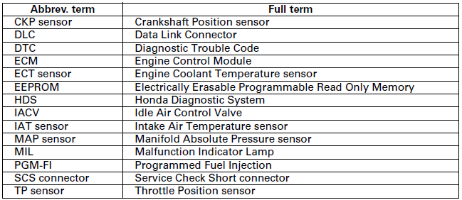
Throughout this manual, the following abbreviations are used to identify the respective parts or systems.
MODEL IDENTIFICATION
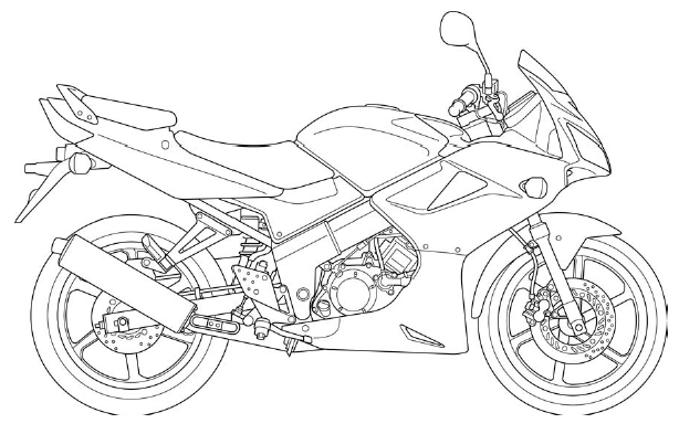
EXCEPT CM AND U model shown:
SERIAL NUMBERS
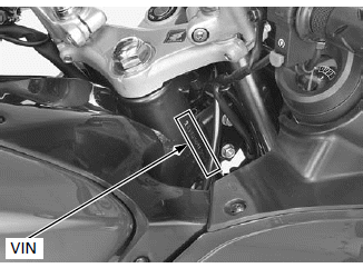
The Vehicle Identification Number (VIN) is stamped on the right side of the steering head.
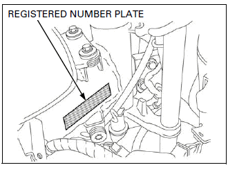
The registered number plate is located on the right side of the frame (Except CM and U type).
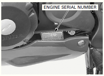
The engine serial number is stamped on the lower left side of the crankcase.
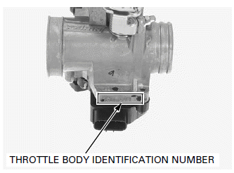
The throttle body identification number is stamped on the right side of the throttle body.
LABELS
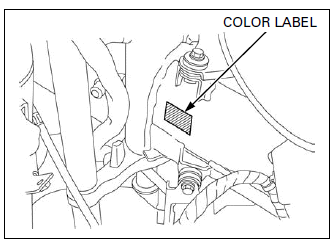
The color label is attached on the left side of the frame.
When ordering color-coded parts, always specify the designated color code.
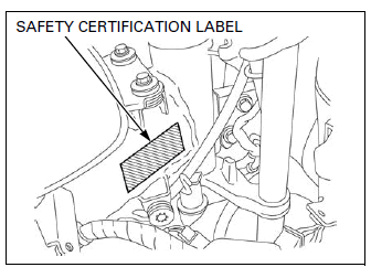
The Safety Certification Label is located on the right side of the frame (CM type only).
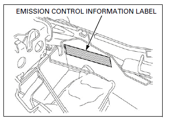
The Emission Control Information Label is located on the rear fender (CM type only).
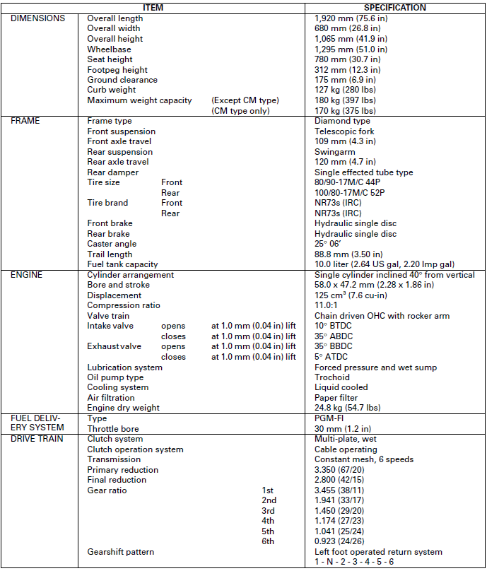
GENERAL SPECIFICATIONS

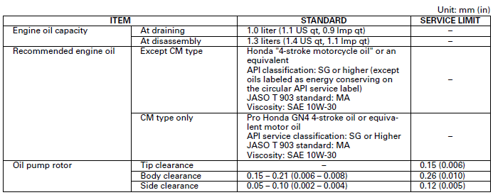
LUBRICATION SYSTEM SPECIFICATIONS
FUEL SYSTEM (PGM-FI) SPECIFICATIONS

COOLING SYSTEM SPECIFICATIONS

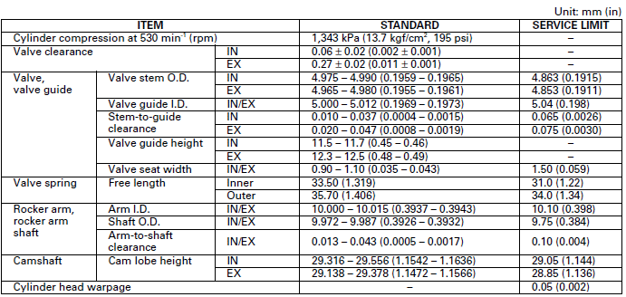
CYLINDER HEAD/VALVES SPECIFICATIONS
CYLINDER/PISTON SPECIFICATIONS
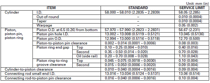
CLUTCH/GEARSHIFT LINKAGE SPECIFICATIONS

ALTERNATOR/STARTER CLUTCH SPECIFICATIONS

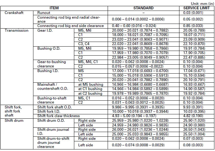
CRANKSHAFT/BALANCER/TRANSMISSION SPECIFICATIONS
FRONT WHEEL/SUSPENSION/STEERING SPECIFICATIONS
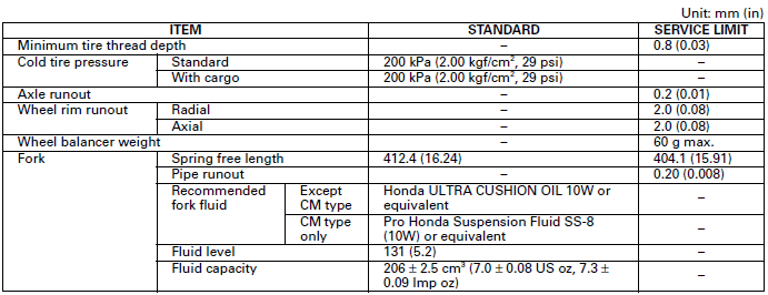
REAR WHEEL/SUSPENSION SPECIFICATIONS

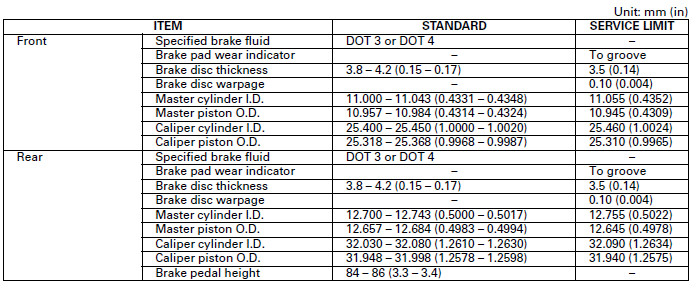
HYDRAULIC BRAKE SPECIFICATIONS
BATTERY/CHARGING SYSTEM SPECIFICATIONS

IGNITION SYSTEM SPECIFICATIONS

ELECTRIC STARTER SPECIFICATION

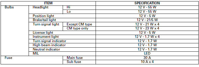
LIGHTS/METERS/SWITCHES SPECIFICATIONS
STANDARD TORQUE VALUES

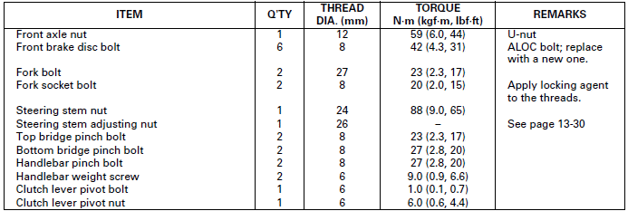
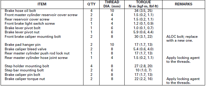
ENGINE & FRAME TORQUE VALUES
- Torque specifications listed below are for important fasteners.
- Others should be tightened to standard torque values listed above.
BODY PANELS/EXHAUST SYSTEM

MAINTENANCE

LUBRICATION SYSTEM

FUEL SYSTEM (PGM-FI)

COOLING SYSTEM

ENGINE REMOVAL/INSTALLATION

CYLINDER HEAD/VALVES

CYLINDER/PISTON

CLUTCH/GEARSHIFT LINKAGE

ALTERNATOR/STARTER CLUTCH

FRONT WHEEL/SUSPENSION/STEERING
REAR WHEEL/SUSPENSION

HYDRAULIC BRAKE
IGNITION SYSTEM

LIGHTS/METERS/SWITCHES

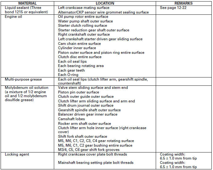
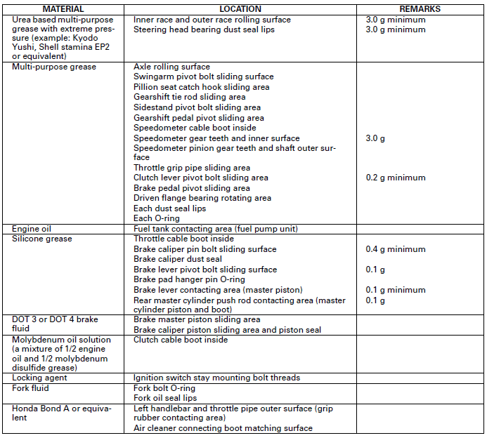
LUBRICATION & SEAL POINTS
ENGINE
FRAME
CABLE & HARNESS ROUTING
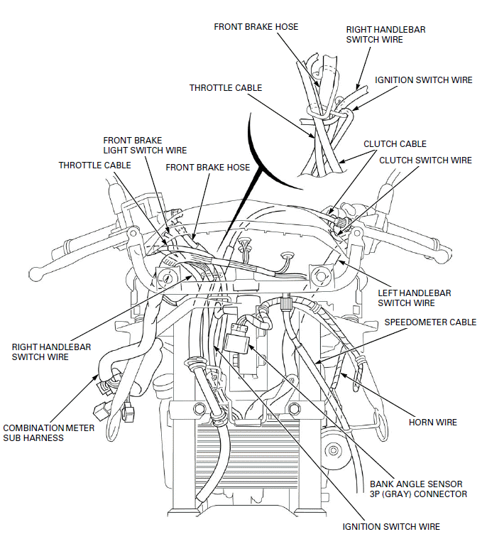
- THROTTLE CABLE
- FRONT BRAKE LIGHT SWITCH WIRE
- FRONT BRAKE HOSE
- THROTTLE CABLE
- CLUTCH CABLE
- CLUTCH SWITCH WIRE
- LEFT HANDLEBAR SWITCH WIRE
- SPEEDOMETER CABLE
- HORN WIRE
- BANK ANGLE SENSOR 3P (GRAY) CONNECTOR
- IGNITION SWITCH WIRE
- COMBINATION METER SUB HARNESS
- RIGHT HANDLEBAR SWITCH WIRE
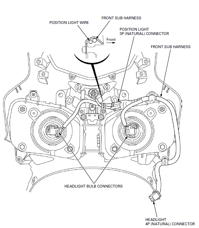
- POSITION LIGHT WIRE
- POSITION LIGHT 3P (NATURAL) CONNECTOR
- FRONT SUB HARNESS
- HEADLIGHT 4P (NATURAL) CONNECTOR
- HEADLIGHT BULB CONNECTORS
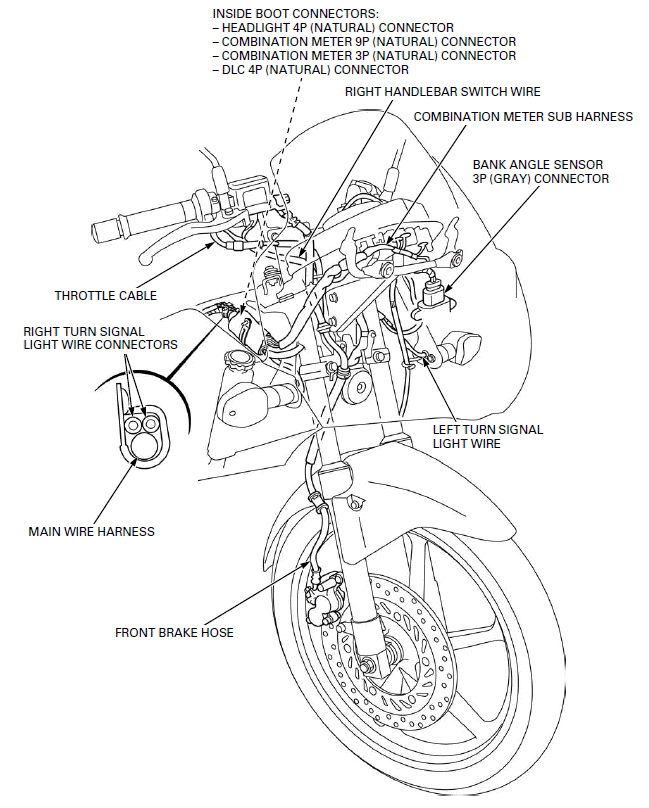
- THROTTLE CABLE
- RIGHT TURN SIGNAL LIGHT WIRE CONNECTORS
- MAIN WIRE HARNESS
- FRONT BRAKE HOSE
- LEFT TURN SIGNAL LIGHT WIRE
- BANK ANGLE SENSOR 3P (GRAY) CONNECTOR
- COMBINATION METER SUB HARNESS
- RIGHT HANDLEBAR SWITCH WIRE
- INSIDE BOOT CONNECTORS:
- HEADLIGHT 4P (NATURAL) CONNECTOR
- COMBINATION METER 9P (NATURAL) CONNECTOR
- COMBINATION METER 3P (NATURAL) CONNECTOR
- DLC 4P (NATURAL) CONNECTOR
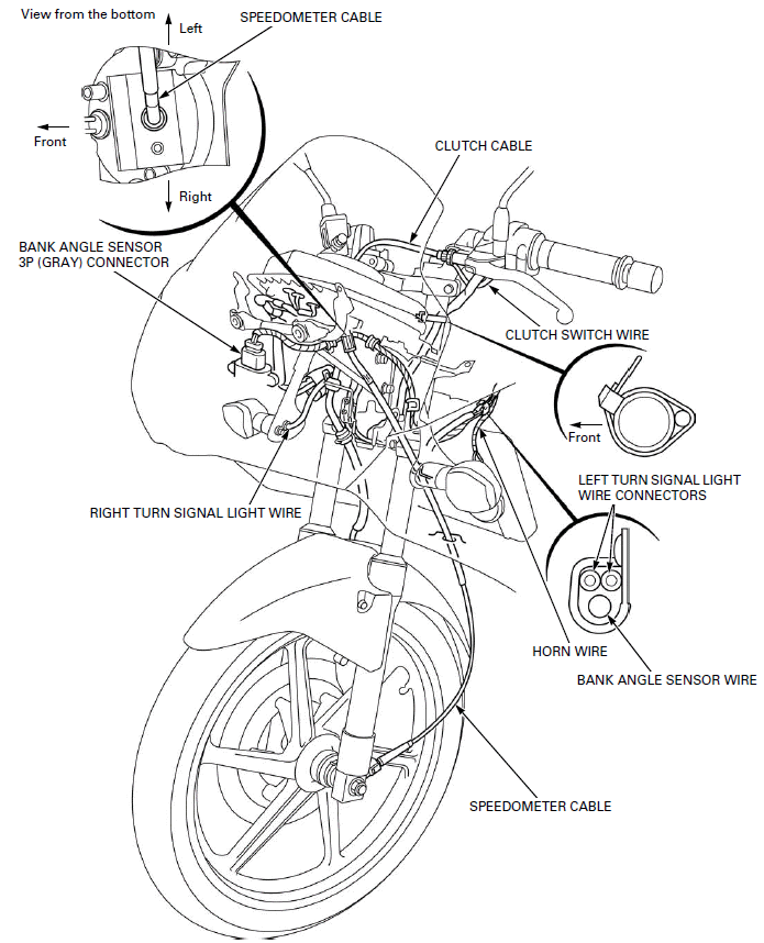
- BANK ANGLE SENSOR 3P (GRAY) CONNECTOR
- RIGHT TURN SIGNAL LIGHT WIRE
- HORN WIRE
- BANK ANGLE SENSOR WIRE
- LEFT TURN SIGNAL LIGHT WIRE CONNECTORS
- CLUTCH SWITCH WIRE
- CLUTCH CABLE
- SPEEDOMETER CABLE
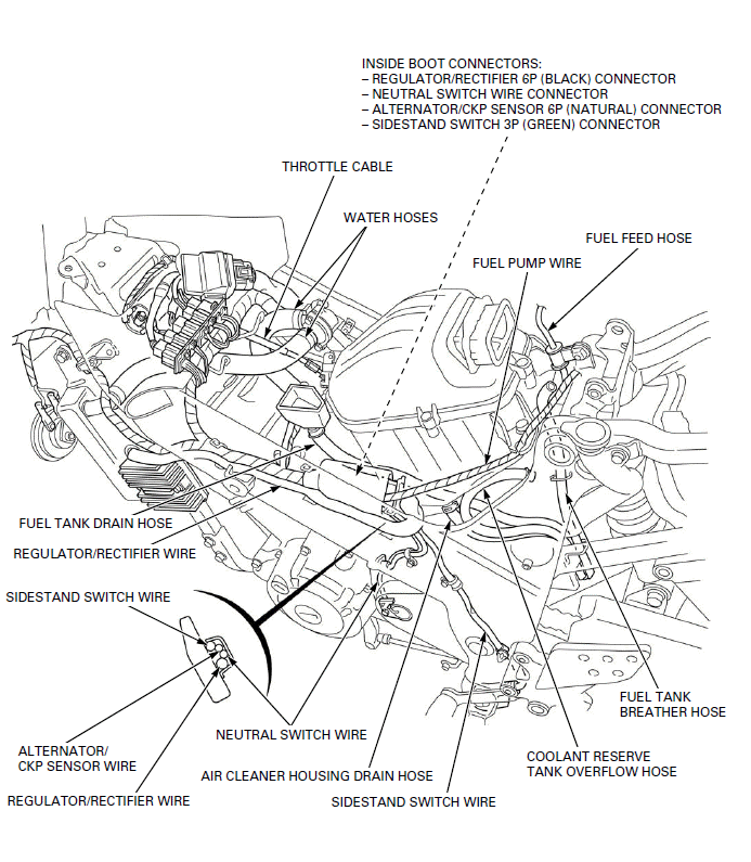
- THROTTLE CABLE
- WATER HOSES
- INSIDE BOOT CONNECTORS:
- REGULATOR/RECTIFIER 6P (BLACK) CONNECTOR
- NEUTRAL SWITCH WIRE CONNECTOR
- ALTERNATOR/CKP SENSOR 6P (NATURAL) CONNECTOR
- SIDESTAND SWITCH 3P (GREEN) CONNECTOR
- FUEL PUMP WIRE
- FUEL FEED HOSE
- FUEL TANK BREATHER HOSE
- COOLANT RESERVE TANK OVERFLOW HOSE
- SIDESTAND SWITCH WIRE
- AIR CLEANER HOUSING DRAIN HOSE
- NEUTRAL SWITCH WIRE
- REGULATOR/RECTIFIER WIRE
- ALTERNATOR/ CKP SENSOR WIRE
- SIDESTAND SWITCH WIRE
- REGULATOR/RECTIFIER WIRE
- FUEL TANK DRAIN HOSE
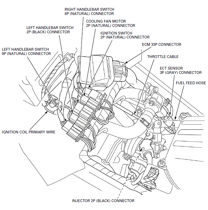
- LEFT HANDLEBAR SWITCH 9P (NATURAL) CONNECTOR
- LEFT HANDLEBAR SWITCH 2P (BLACK) CONNECTOR
- RIGHT HANDLEBAR SWITCH 6P (NATURAL) CONNECTOR
- COOLING FAN MOTOR 2P (NATURAL) CONNECTOR
- IGNITION SWITCH 2P (NATURAL) CONNECTOR
- ECM 33P CONNECTOR
- THROTTLE CABLE
- ECT SENSOR 3P (GRAY) CONNECTOR
- FUEL FEED HOSE
- INJECTOR 2P (BLACK) CONNECTOR
- IGNITION COIL PRIMARY WIRE

- REAR BRAKE LIGHT SWITCH
- REAR BRAKE LIGHT SWITCH 2P (NATURAL) CONNECTOR
- FUEL FEED HOSE
- SIPHON HOSE
- GROUND CABLE
- STARTER MOTOR CABLE
- MAIN WIRE HARNESS
- SIPHON HOSE
- WATER HOSE
- WATER PUMP INSPECTION HOSE
- CLUTCH CABLE
- AIR CLEANER HOUSING DRAIN HOSE
- COOLANT RESERVE TANK OVERFLOW HOSE
- FUEL TANK DRAIN HOSE
- AIR CLEANER HOUSING DRAIN HOSE
- FUEL TANK BREATHER HOSE
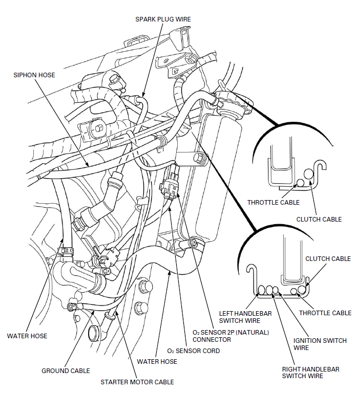
- SPARK PLUG WIRE
- THROTTLE CABLE
- CLUTCH CABLE
- IGNITION SWITCH WIRE
- RIGHT HANDLEBAR SWITCH WIRE
- LEFT HANDLEBAR SWITCH WIRE
- O2 SENSOR 2P (NATURAL) CONNECTOR
- O2 SENSOR CORD
- STARTER MOTOR CABLE
- GROUND CABLE
- WATER HOSE
- SIPHON HOSE
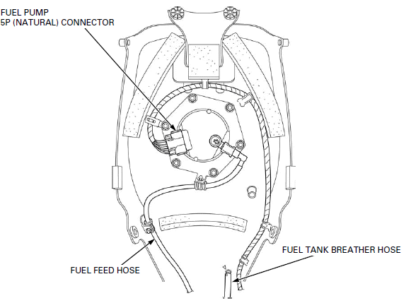
- FUEL PUMP 5P (NATURAL) CONNECTOR
- FUEL FEED HOSE
- FUEL TANK BREATHER HOSE
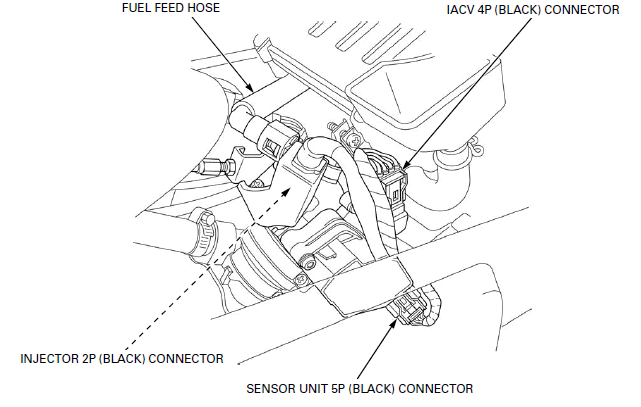
- FUEL FEED HOSE
- IACV 4P (BLACK) CONNECTOR
- INJECTOR 2P (BLACK) CONNECTOR
- SENSOR UNIT 5P (BLACK) CONNECTOR
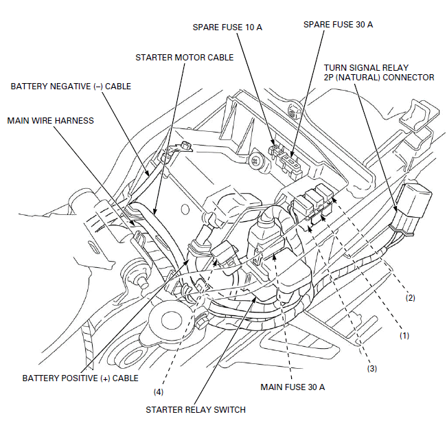
- MAIN WIRE HARNESS
- BATTERY NEGATIVE (-) CABLE
- STARTER MOTOR CABLE
- SPARE FUSE 10 A
- SPARE FUSE 30 A
- TURN SIGNAL RELAY 2P (NATURAL) CONNECTOR
- MAIN FUSE 30 A
- STARTER RELAY SWITCH
- BATTERY POSITIVE (+) CABLE
SUB FUSE 10 A:
- SUB FUSE A
- FUN MOTOR
- SUB FUSE B
- BRAKE/TAIL LIGHT
- TURN SIGNAL LIGHT
- TURN SIGNAL INDICATOR
- LICENSE LIGHT
- MIL
- INSTRUMENT LIGHT
- NEUTRAL INDICATOR
- POSITION LIGHT
- HORN
- SUB FUSE C
- HEADLIGHT
- HIGH BEAM INDICATOR
- TACHOMETER
- COOLANT TEMPERATURE GAUGE
- FUEL GAUGE
- SUB FUSE D
- FUEL PUMP
- IGNITION COIL
- ECM
- INJECTOR
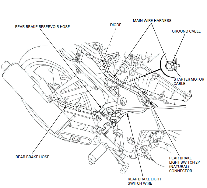
- REAR BRAKE RESERVOIR HOSE
- REAR BRAKE HOSE
- REAR BRAKE LIGHT SWITCH WIRE
- REAR BRAKE LIGHT SWITCH 2P (NATURAL) CONNECTOR
- STARTER MOTOR CABLE
- GROUND CABLE
- MAIN WIRE HARNESS
- DIODE
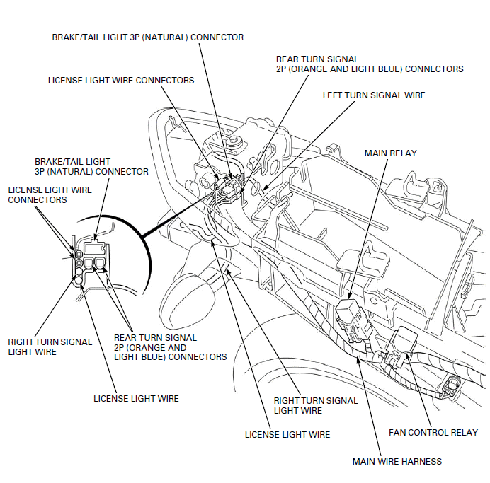
- LICENSE LIGHT WIRE CONNECTORS
- BRAKE/TAIL LIGHT 3P (NATURAL) CONNECTOR
- REAR TURN SIGNAL 2P (ORANGE AND LIGHT BLUE) CONNECTORS
- LEFT TURN SIGNAL WIRE
- MAIN RELAY
- FAN CONTROL RELAY
- MAIN WIRE HARNESS
- RIGHT TURN SIGNAL LIGHT WIRE
EMISSION CONTROL SYSTEMS (Except CM type)
SOURCE OF EMISSIONS
The combustion process produces carbon monoxide (CO), oxides of nitrogen (NOx) and hydrocarbons (HC). Control of carbon monoxide, oxides of nitrogen and hydrocarbons is very important because, under certain conditions, they react to form photochemical smog when subject to sunlight. Carbon monoxide does not react in the same way, but it is toxic.
Honda Motor Co., Ltd. utilizes various systems to reduce carbon monoxide, oxides of nitrogen and hydrocarbons.
CRANKCASE EMISSION CONTROL SYSTEM
The engine is equipped with a closed crankcase system to prevent discharging crankcase emissions into the atmosphere.
Blow-by gas is returned to the combustion chamber through the air cleaner housing and throttle body.
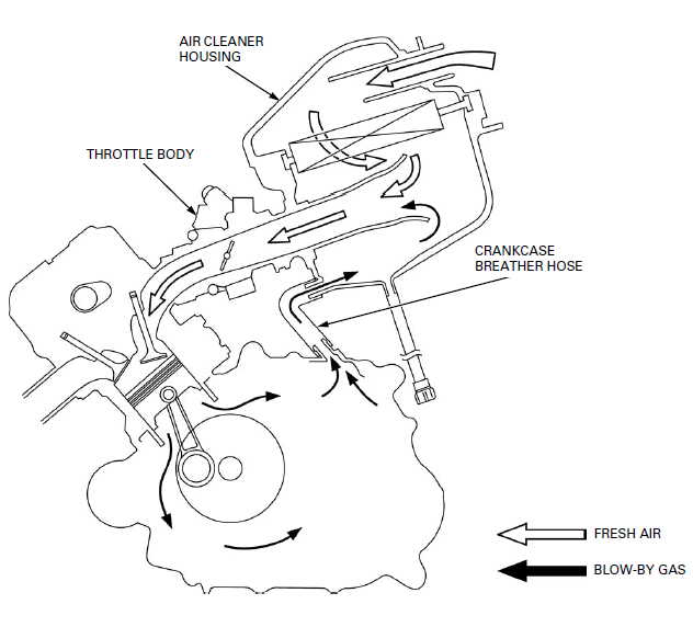
- AIR CLEANER HOUSING
- THROTTLE BODY
- CRANKCASE BREATHER HOSE
EXHAUST EMISSION CONTROL SYSTEM
The exhaust emission control system is composed of a three-way catalytic converter and PGM-FI system.
THREE-WAY CATALYTIC CONVERTER
This motorcycle is equipped with a three-way catalytic converter.
The three-way catalytic converter is in the exhaust system. Through chemical reactions, it converts HC, CO and NOx in the engine's exhaust to carbon dioxide (CO2), nitrogen (N2), and water vapor.
No adjustment to these systems should be made although periodic inspection of the components is recommended.
NOISE EMISSION CONTROL SYSTEM (Except U type)
TAMPERING WITH THE NOISE CONTROL SYSTEM IS PROHIBITED:
Local law may prohibit the following acts or the causing there of: (1) The removal or rendering inoperative by any person, other than for purposes of maintenance, repair or replacement, of any device or element of design incorporated into any vehicle for the purpose of noise control prior to its sale or delivery to the ultimate customer or while it is in use; (2) the use of the vehicle after such device or element of design has been removed or rendered inoperative by any person.
AMONG THOSE ACTS PRESUMED TO CONSTITUTE TAMPERING ARE THE ACTS LISTED BELOW:
1. Removal of, or puncturing of the muffler, baffles, header pipes or any other component which conducts exhaust gases.
2. Removal of, or puncturing of any part of the intake system.
3. Lack of proper maintenance.
4. Replacing any moving parts of the vehicle, or parts of the exhaust or intake system, with parts other than those specified by the manufacturer.
NOISE EMISSION CONTROL SYSTEM (U type only)
TAMPERING WITH THE NOISE CONTROL SYSTEM IS PROHIBITED: Local law may prohibit the following acts or the causing there of: (1) The removal or rendering inoperative by any person, other than for purposes of maintenance, repair or replacement, of any device or element of design incorporated into any vehicle for the purpose of noise control prior to its sale or delivery to the ultimate customer or while it is in use; (2) the use of the vehicle after such device or element of design has been removed or rendered inoperative by any person.
EMISSION CONTROL SYSTEMS (CM type only)
EXHAUST EMISSION REQUIREMENT
The U.S. Environmental Protection Agency (EPA), California Air Resources Board (CARB) and Transport Canada require manufacturers to certify that their motorcycles comply with applicable exhaust emissions standards during their useful life, when operated and maintained according to the instructions provided.
NOISE EMISSION REQUIREMENT
The EPA also requires that motorcycles built after January 1, 1983 comply with applicable noise emission standards for one year or 3,730 miles (6,000 km) after the time of sale to the ultimate purchaser, when operated and maintained according to the instructions provided.
WARRANTY COMPLIANCE
Compliance with the terms of the Distributor's Limited Warranty for Honda Motorcycle Emission Control Systems is necessary in order to keep the emissions system warranty in effect.
SOURCE OF EMISSIONS
The combustion process produces carbon monoxide (CO), oxides of nitrogen (NOx) and hydrocarbons (HC). Control of carbon monoxide, oxides of nitrogen and hydrocarbons is very important because, under certain conditions, they react to form photochemical smog when subject to sunlight. Carbon monoxide does not react in the same way, but it is toxic.
Honda Motor Co., Ltd. utilizes various systems to reduce carbon monoxide, oxides of nitrogen and hydrocarbons.
CRANKCASE EMISSION CONTROL SYSTEM
The engine is equipped with a closed crankcase system to prevent discharging crankcase emissions into the atmosphere.
Blow-by gas is returned to the combustion chamber through the air cleaner housing and throttle body.
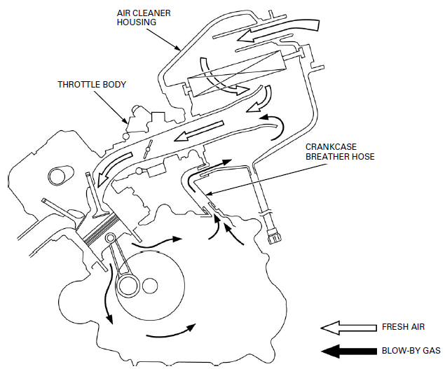
- AIR CLEANER HOUSING
- THROTTLE BODY
- CRANKCASE BREATHER HOSE
EXHAUST EMISSION CONTROL SYSTEM
The exhaust emission control system is composed of a three-way catalytic converter and PGM-FI system.
THREE-WAY CATALYTIC CONVERTER
This motorcycle is equipped with a three-way catalytic converter.
The three-way catalytic converter is in the exhaust system. Through chemical reactions, it converts HC, CO and NOx in the engine's exhaust to carbon dioxide (CO2), nitrogen (N2), and water vapor.
No adjustment to these systems should be made although periodic inspection of the components is recommended.
NOISE EMISSION CONTROL SYSTEM
TAMPERING WITH THE NOISE CONTROL SYSTEM IS PROHIBITED:
U.S. Federal law prohibits, or Canadian provincial law may prohibit the following acts or the causing there of: (1) The removal or rendering inoperative by any person, other than for purposes of maintenance, repair or replacement, of any device or element of design incorporated into any vehicle for the purpose of noise control prior to its sale or delivery to the ultimate customer or while it is in use; (2) the use of the vehicle after such device or element of design has been removed or rendered inoperative by any person.
AMONG THOSE ACTS PRESUMED TO CONSTITUTE TAMPERING ARE THE ACTS LISTED BELOW:
1. Removal of, or puncturing of the muffler, baffles, header pipes or any other component which conducts exhaust gases.
2. Removal of, or puncturing of any part of the intake system.
3. Lack of proper maintenance.
4. Replacing any moving parts of the vehicle, or parts of the exhaust or intake system, with parts other than those specified by the manufacturer.
See also:
 Honda CBR125RW - Service manual > Safety
A Few Words About Safety Service Information The service and repair information contained in this manual is intended for use by qualified, professional technicians.
 Honda CBR125RW - Service manual > Body Panels/Exhaust System
BODY PANEL LOCATIONS EXCEPT CM AND U TYPE shown: WINDSCREEN UPPER COWL FRONT FENDER MIDDLE COWL LOWER COWL REAR COWL INNER COWL FUEL TANK COVER REAR FENDER GRAB RAIL PILLION SEAT SINGLE SEAT

 BMW G310GS
 Honda CBR125RW
 Husqvarna 401 Vitpilen
 KTM 890 Duke R
 Mash Dirt Track 650
 Peugeot Kisbee
 Yamaha Tracer MT-09
 Honda CBR125RW
 Peugeot Kisbee
 Yamaha Tracer MT-09