 Honda CBR125RW - Service manual > Body Panels/Exhaust System
BODY PANEL LOCATIONS
EXCEPT CM AND U TYPE shown:
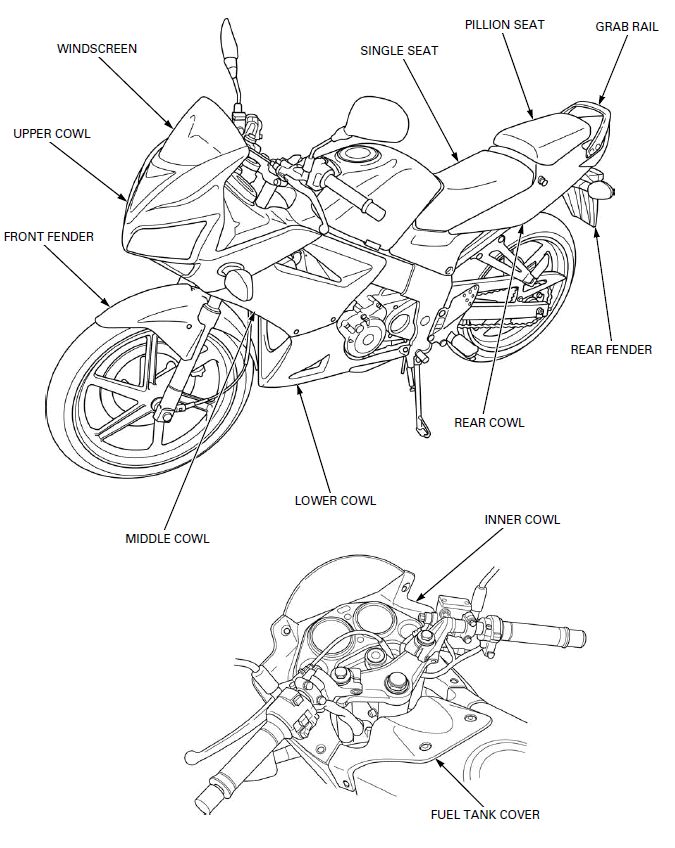
- WINDSCREEN
- UPPER COWL
- FRONT FENDER
- MIDDLE COWL
- LOWER COWL
- REAR COWL
- INNER COWL
- FUEL TANK COVER
- REAR FENDER
- GRAB RAIL
- PILLION SEAT
- SINGLE SEAT
SERVICE INFORMATION
GENERAL
- This section covers removal and installation of the body panels and exhaust system.
- Serious burns may result if the exhaust system is not allowed to cool before components are removed or serviced.
- Always replace the exhaust pipe gasket with new ones after removing the exhaust pipe from the engine.
- When installing the exhaust system, loosely install all of the exhaust pipe fasteners. Always tighten the exhaust pipe joint nuts first, then tighten the mounting bolts.
- Always inspect the exhaust system for leaks after installation.
TORQUE VALUES
Grab rail mounting bolt 27 N-m (2.8 kgf-m, 20 lbf-ft)
Turn signal light mounting nut 8.8 N-m (0.9 kgf-m, 6.5 lbf-ft)
Muffler joint bolt 13 N-m (1.3 kgf-m, 10 lbf-ft)
Exhaust pipe cover bolt 13 N-m (1.3 kgf-m, 10 lbf-ft)
Exhaust pipe stud bolt -
TROUBLESHOOTING
Excessive exhaust noise
- Broken exhaust system
- Exhaust gas leak
Poor performance
- Deformed exhaust system
- Exhaust gas leak
- Clogged muffler
PILLION SEAT
REMOVAL/INSTALLATION
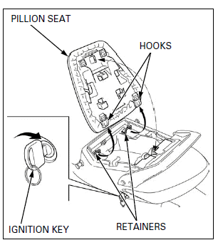
Unhook the pillion seat lock using the ignition key.
Remove the pillion seat by pulling it rearward.
Install the pillion seat by inserting the hooks into the seat retainers.
Push the pillion seat down to lock it.
SINGLE SEAT
REMOVAL/INSTALLATION
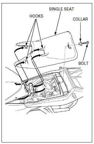
Remove the pillion seat.
Remove the mounting bolt and collar.
Remove the single seat by pulling it rearward.
Install the single seat hooks under the seat bracket on the frame and fuel tank.
Install the collar and mounting bolt, tighten the mounting bolt securely.
GRAB RAIL
REMOVAL/INSTALLATION
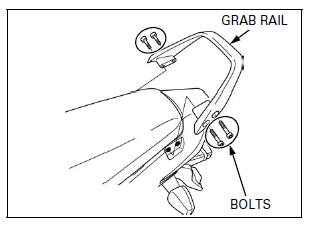
Remove the mounting bolts and grab rail.
Install the grab rail and mounting bolts, tighten the bolts to the specified torque.
TORQUE: 27 N-m (2.8 kgf-m, 20 lbf-ft)
REAR COWL
REMOVAL/INSTALLATION
Remove the following:
- Single seat
- Grab rail
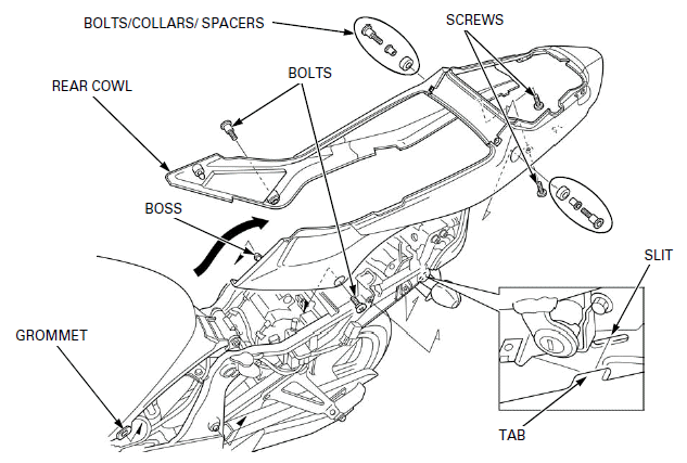
Remove the bolts, collars, spacers and screws.
Release the bosses from the grommets of the fuel tank.
Be careful not to damage the rear cowl.
Carefully pull out both sides of the rear cowl, then remove it rearward.
Install the rear cowl in the reverse order of removal.
NOTE:
Insert the tabs to the slits of the rear fender.
DISASSEMBLY/ASSEMBLY
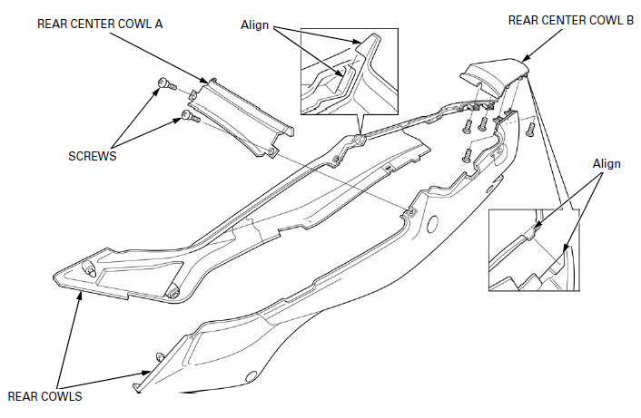
Remove the screws, rear center cowl A and B from the rear cowls.
Assembly is in the reverse order of disassembly.
NOTE:
Install the rear center cowl A and B by aligning its tabs with the slits of the both rear cowls.
FUEL TANK COVER
REMOVAL/INSTALLATION
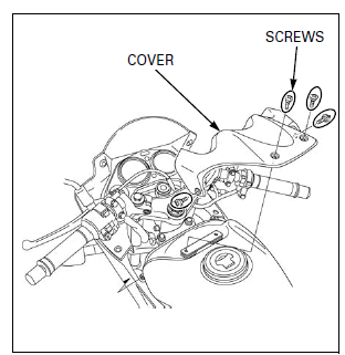
Remove the screws and fuel tank cover.
Install the fuel tank cover and screws.
INNER COWL
REMOVAL/INSTALLATION
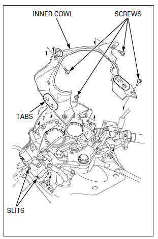
Remove the screws and inner cowl by pulling it rearward.
Install the inner cowl in the reverse order of removal.
NOTE:
Insert the tabs of the inner cowl to the slits of the middle cowl and upper cowl.
LOWER COWL
REMOVAL/INSTALLATION
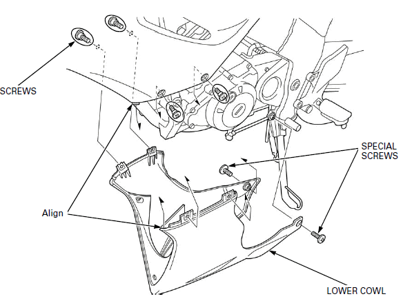
Remove the lower cowl special screws.
Be careful not to damage the tabs and slits.
Remove the lower cowl special screws.
Remove the lower cowl-to-middle cowl screws and then remove the lower cowl downward.
Install the lower cowl by aligning the tabs of the middle cowl with the slits of the lower cowl.
Install and tighten the lower cowl-to-middle cowl screws.
Install and tighten the lower cowl special screws.
DISASSEMBLY/ASSEMBLY
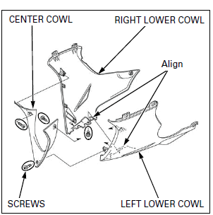
Remove the screws and lower center cowl.
Be careful not to damage the tabs.
Remove the screws and separate the right and left lower cowls.
Assemble the lower cowl in the reverse order of disassembly.
NOTE:
Assemble the right and left lower cowls by aligning its tabs with the slits.
MIDDLE COWL
REMOVAL/INSTALLATION
Remove the following:
- Fuel tank cover
- Inner cowl
- Lower cowl
- Turn signal light
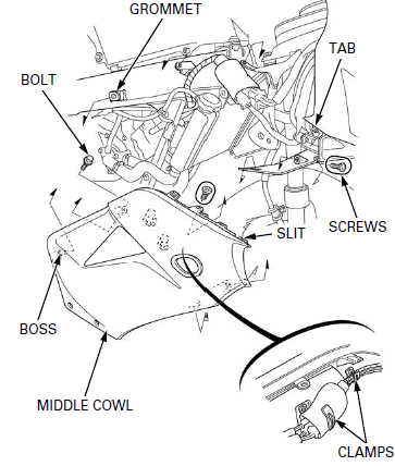
Release the wires from the clamps.
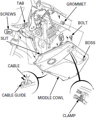
Remove the screws and bolts.
Be careful not to damage the tabs and slits.
Release the boss from the grommet of the frame and remove the middle cowl by pulling it forward.
LEFT SIDE:
Release the speedometer cable from the cable guide.
Route the wires properly.
Install the middle cowl in the reverse order of removal.
RIGHT SIDE:
LEFT SIDE:
UPPER COWL
REMOVAL/INSTALLATION
Remove the middle cowl.
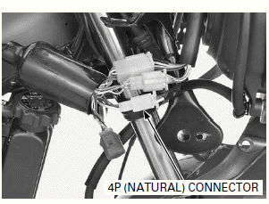
Disconnect the headlight/position light 4P (Natural) connector.
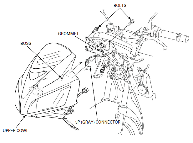
Remove the bolts and release the bosses from the grommets of the upper cowl stay.
Disconnect the bank angle sensor 3P (Gray) connector.
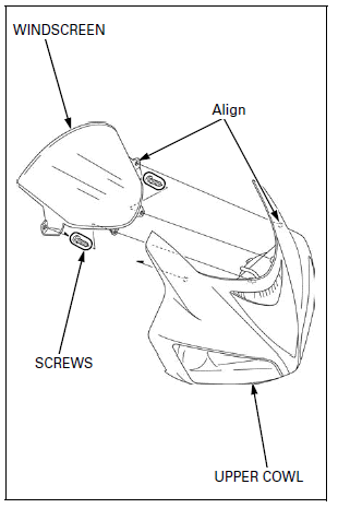
Remove the screws and windscreen.
Install the windscreen by aligning its holes with the bosses of the upper cowl.
Install and tighten the screws.
Install the upper cowl in the reverse order of removal.
FRONT FENDER
REMOVAL/INSTALLATION
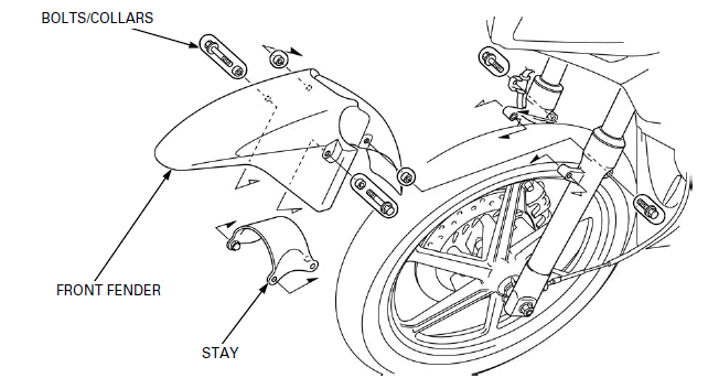
Be careful not to damage the fork legs.
Remove the bolts, collars, front fender and front fender stay from the fork legs.
NOTE:
Pull the front fender up and then pull it forward between the fork legs.
Install the front fender in the reverse order of removal.
REAR FENDER
REMOVAL/INSTALLATION
Remove the following:
- Brake/tail light
- Battery
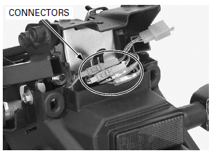
Disconnect the turn signal light 2P (Orange and Light blue) connectors and license light connectors.
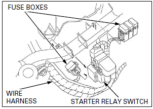
Remove the starter relay switch and fuse boxes.
Release the wire harness from the rear fender.
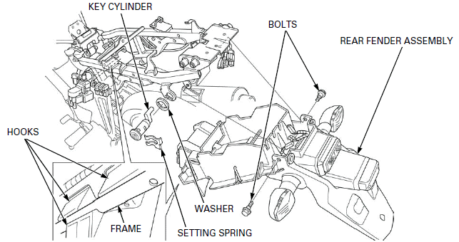
Remove the setting spring, seat lock key cylinder and retaining washer from the rear fender.
Remove the bolts and rear fender by pulling it rearward.
Route the wires properly.
Install the rear fender in the reverse order of removal.
NOTE:
Insert the hooks of the rear fender into the frame.
DISASSEMBLY/ASSEMBLY
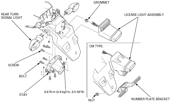
Remove the following:
- Turn signal light mounting nuts and turn signal lights
- Bolts and turn signal light stay
- Screws and license light assembly
- Grommet
- Nuts and number plate bracket (CM type)
Assemble is in the reverse order of disassembly.
EXCEPT CM TYPE:
EXHAUST PIPE/MUFFLER
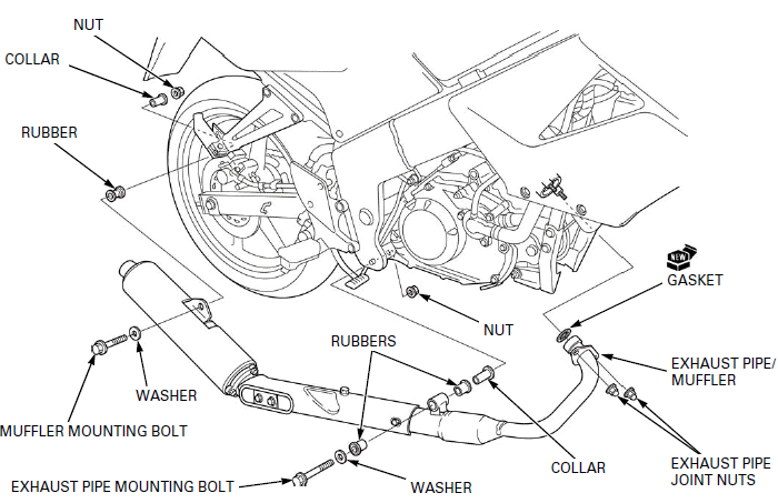
REMOVAL
Remove the lower cowl.
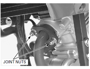
Remove the exhaust pipe joint nuts.
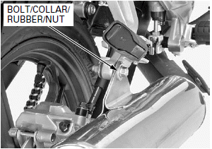
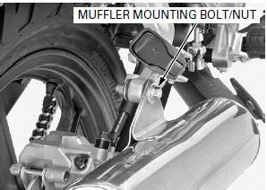
Remove the muffler mounting bolt, collar, rubber and nut.
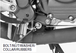
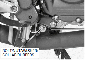
Remove the exhaust pipe mounting bolt, nut, washer, collar and rubbers.
Remove the exhaust pipe/muffler as assembly.
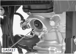
Remove the exhaust pipe gasket.
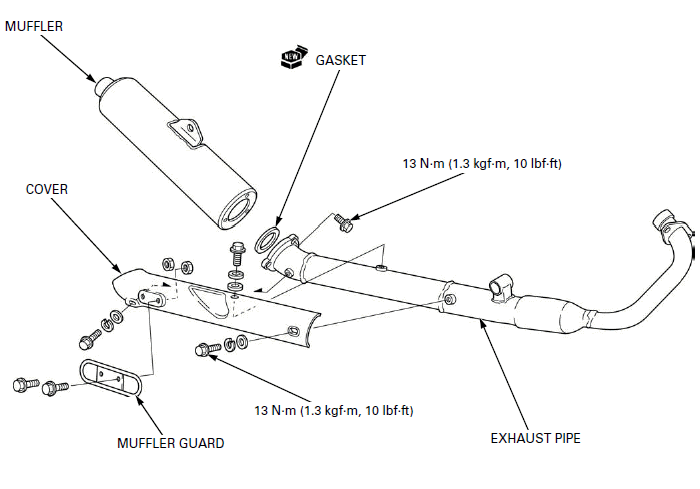
DISASSEMBLY/ASSEMBLY
Remove the following:
- Bolts, spring washers, washers and exhaust pipe cover
- Bolts, nuts and muffler guard
- Bolts, muffler and gasket
Assembly is in the reverse order of disassembly.
NOTE:
Always replace the muffler gasket with a new one whenever the muffler is removed from the exhaust pipe.
TORQUE:
Muffler joint bolt: 13 N-m (1.3 kgf-m, 10 lbf-ft)
Exhaust pipe cover bolt: 13 N-m (1.3 kgf-m, 10 lbf-ft)
INSTALLATION
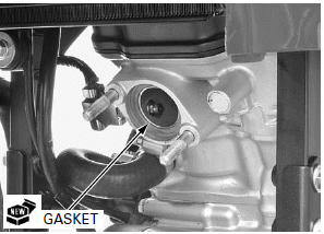
Install a new exhaust pipe gasket to the exhaust port of the cylinder head.
NOTE:
Always replace the exhaust pipe gasket with a new one whenever the exhaust pipe is removed.
Install the exhaust pipe/muffler, then temporarily install the all mounting fasteners.
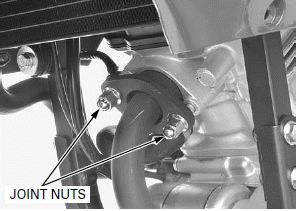
Tighten the exhaust pipe joint nuts securely.
Tighten the exhaust pipe mounting bolt and nut securely.
Tighten the muffler mounting bolt and nut securely.
After the installation, inspect the exhaust system for leaks.
STUD BOLT REPLACEMENT
Remove the exhaust pipe/muffler.
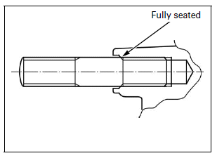
Thread two nuts onto the stud and tighten them together, and use a wrench on them to turn the stud bolt out.
Install new stud bolts into the cylinder head until it is fully seated as shown.
Install the exhaust pipe/muffler.
See also:
 Honda CBR125RW - Service manual > General Information
SERVICE RULES 1. Use genuine Honda or Honda-recommended parts and lubricants or their equivalents. Parts that do not meet Honda's design specifications may cause damage to the motorcycle.
 Honda CBR125RW - Service manual > Maintenance
SERVICE INFORMATION GENERAL Place the motorcycle on level surface before starting any work. Gasoline is extremely flammable and is explosive under certain conditions. Work in a well ventilated area. Smoking or allowing flames or sparks in the work area or where the gasoline is stored can cause a fire or explosion. The exhaust contains poisonous carbon monoxide gas that may cause loss of consciousness and may lead to death.

 BMW G310GS
 Honda CBR125RW
 Husqvarna 401 Vitpilen
 KTM 890 Duke R
 Mash Dirt Track 650
 Peugeot Kisbee
 Yamaha Tracer MT-09
 Honda CBR125RW
 Peugeot Kisbee
 Yamaha Tracer MT-09