 Yamaha Tracer MT09TRA - Service manual > Throttle bodies


Checking the injectors (before removing)
1. Check:
- Injectors
Removing the fuel hose (fuel rail side)
1. Remove:
- Fuel tank
2. Remove:
- Fuel hose (fuel rail side)
NOTICE
Be sure to disconnect the fuel hose by hand.
Do not forcefully disconnect the hose with tools.
TIP
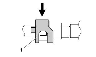
- To remove the fuel hose from the fuel rail joint, slide the fuel hose connector cover "1" on the end of the hose in the direction of the arrow shown, press the two buttons "2" on the sides of the connector, and then remove the hose.
- Before removing the hose, place a few rags in the area under where it will be removed.
- It is prohibited to wear the cotton work gloves or equivalent coverings.
Removing the injectors

WARNING
- Check the injectors in a well-ventilated area free of combustible materials. Make sure that there is no smoking or use of electric tools in the vicinity of the injectors.
- Be careful when disconnecting the fuel hose. Any remaining pressure in the fuel hose may cause the fuel to spray out. Place a container or rag under the hose to catch any fuel that spills. Always clean up any spilt fuel immediately.
- Turn the main switch to "OFF" and disconnect the negative battery lead from the battery terminal before removing the injectors.
1. Remove:
- Throttle bodies
- Fuel rail "1"
a. Remove the fuel rail bolts "2" as shown.

Checking the injectors
1. Check:
- Injectors
Obstruction → Replace and check the fuel pump/fuel supply system.
Deposit → Replace.
Damage → Replace.
2. Check:
- Injector resistance
Checking and cleaning the throttle bodies
TIP
Clean the throttle bodies only if they cannot be synchronized using the bypass air screws. Before cleaning the throttle bodies, check the following items:
- Valve clearance
- Spark plugs
- Air filter element
- Throttle body joints
- Fuel hose
- Exhaust system
- Cylinder head breather hose
WARNING
If the throttle bodies are subjected to strong shocks or dropped during cleaning, replace them as a set.
1. Check:
- Throttle bodies
Cracks/damage → Replace the throttle bodies as a set.
2. Clean:
- Throttle bodies
NOTICE
- Observe the following precautions; otherwise, the throttle bodies may not operate properly.
- Do not subject the throttle bodies to excessive force.
- Clean the throttle bodies in the recommended cleaning solvent.
- Do not use any caustic carburetor cleaning solution.
- Do not apply cleaning solvent directly to any plastic parts, sensors, or seals.
- Be careful not to remove the white paint mark that identifies the standard throttle body.
- Do not turn the bypass air screws "a"; otherwise, the throttle body synchronization will be affected.
 Recommended cleaning solvent
Yamaha Oil & Brake Cleaner

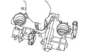
a. Place the throttle bodies on a flat surface with the air filter case side facing up.
b. Install the caps (895-14169-00) onto the hose fittings "a".

c. Hold the throttle valves in the open position.
WARNING
When cleaning the throttle bodies, be careful not to injure yourself on the throttle valves or other components of the throttle bodies.
NOTICE
- Do not open the throttle valves by supplying electrical power to the throttle bodies.
- Do not use tools to open the throttle valves or to keep them in the open position.
- Do not open the throttle valves quickly.

d. Apply the recommended cleaning solvent to the throttle valves and the inside of the throttle bodies to remove any carbon deposits.
TIP
- Do not allow any cleaning solvent to enter the opening for the injectors.
- Do not apply any cleaning solvent to the portions of the throttle valve shafts between the throttle bodies
e. Remove the carbon deposits from the inside of each throttle body in a downward direction, from the air filter case side of the throttle body to the engine side.
NOTICE
- Do not use a tool, such as a wire brush, to remove the carbon deposits; otherwise, the inside of the throttle bodies may be damaged.
- Do not allow carbon deposits or other foreign materials to enter any of the passages in each throttle body or in the space between the throttle valve shaft and the throttle body.
f. After removing the carbon deposits, clean the inside of the throttle bodies with the recommended cleaning solvent, and then dry the throttle bodies using compressed air.
g. Make sure that there are no carbon deposits or other foreign materials in any of the passages "a" in each throttle body or in the space "b" between the throttle valve shaft and the throttle body.

3. Install the throttle bodies.
4. Reset:
- ISC (idle speed control) learning values Use the diagnostic code number "67".
5. Adjust:
- Throttle bodies synchronizing
Out of specification → Replace the throttle bodies.
Replacing the throttle bodies
1. Remove the throttle bodies from the vehicle.
2. Install a new throttle bodies to the vehicle.
3. Reset:
- ISC (idle speed control) learning values Use the diagnostic code number "67".
4. Adjust:
- Throttle bodies synchronizing
5. Place the vehicle on the centerstand so that the rear wheel is elevated.
6. Check:
- Engine idling speed
Start the engine, warm it up, and then measure the engine idling speed.
 Engine idling speed 1100-1300 r/min
Installing the injectors
NOTICE
- Always use new O-rings.
- When installing the injectors, do not allow any foreign material to enter or adhere to the injectors, fuel rails, or O-rings.
- Be careful not to twist or pinch the O-rings when installing the injectors.
- When installing the injector, install it at the same position as the removed cylinder.
- If an injector is subject to strong shocks or excessive force, replace it.
- If installing the original fuel rail and bolts, remove the white paint marks using a cleaning solvent. Otherwise, paint chips on the bolt seats could prevent the bolts from being tightened to the specified torque
1. Install a new seal onto the end of each injector.
2. Install the injectors to the fuel rail, making sure to install them in the correct direction.
3. Install the injector assemblies to the adapter.
 Fuel rail bolt 5 Nm (0.5 m*kgf, 3.6 ft*lbf)
4. Check the injector pressure after the injectors are installed.
Checking the injector pressure
TIP
- After installing the injectors, perform the following steps to check the injector pressure.
- Do not allow any foreign materials to enter the fuel lines.
1. Check:
- Injector pressure
a. Connect the injector pressure adapter "1" to the fuel rail joint "2", and then connect an air compressor "3" to the adapter.
b. Connect the pressure gauge "4" to the injector pressure adapter "1".
 Pressure gauge 90890-03153
Pressure gauge YU-03153
Fuel injector pressure adapter 90890-03210
Fuel injector pressure adapter YU-03210

c. Close the valve on the injector pressure adapter.
d. Apply air pressure with the air compressor.
e. Open the valve on the injector pressure adapter until the specified pressure is reached.
 Specified air pressure 490 kPa (5.0 kgf/cm², 71.1 psi)
NOTICE
Never exceed the specified air pressure or damage could occur.
f. Close the valve on the injector pressure adapter.
g. Check that the specified air pressure is held at least one minute.
Pressure drops → Check the pressure gauge and adapter.
Check the seals and O-rings and then reinstall.
Out of specification → Replace the fuel injectors.
Checking the fuel pressure
1. Remove:
- Fuel tank front cover/Front side panel/Front side cowling
- Passenger seat/Rider seat
- Fuel tank cover
2. Check:
- Fuel pressure
a. Remove the fuel tank bolts and hold up the fuel tank.
b. Disconnect the fuel hose "1" from the fuel pump.
WARNING
Cover fuel hose connections with a cloth when disconnecting them. Residual pressure in the fuel lines could cause fuel to spurt out when removing the hose.
NOTICE
Be sure to disconnect the fuel hose by hand.
Do not forcefully disconnect the hose with tools.

c. Connect the pressure gauge "2" and fuel pressure adapter "3" to the fuel hose.
 Pressure gauge 90890-03153
Pressure gauge YU-03153
Fuel pressure adapter 90890-03176
Fuel pressure adapter YM-03176

d. Start the engine.
e. Measure the fuel pressure.
Faulty → Replace the fuel pump.
 Fuel line pressure at idling 300-390 kPa (3.0-3.9 kgf/cm², 43.5-56.6
psi)
3. Install:
- Fuel tank
- Fuel tank cover
- Rider seat/Passenger seat
- Front side cowling/Front side panel/Fuel tank front cover
Installing the fuel hose (fuel rail side)
1. Connect:
- Fuel hose (fuel rail side)
NOTICE
When installing the fuel hose, make sure that it is securely connected, and that the fuel hose connector cover on the fuel hose is in the correct position, otherwise the fuel hose will not be properly installed.
TIP
- Install the fuel hose securely onto the fuel rail joint until a distinct "click" is heard.
- To install the fuel hose onto the fuel rail joint, slide the fuel hose connector cover "1" on the end of the hose in the direction of the arrow shown.
- It is prohibited to wear the cotton work gloves or equivalent coverings.

Adjusting the throttle position sensor
WARNING
- Handle the throttle position sensor with special care.
- Never subject the throttle position sensor to strong shocks. If the throttle position sensor is dropped, replace it.
1. Check:
- Throttle position sensor
2. Adjust:
- Throttle position sensor angle
TIP
Before adjusting the throttle position sensor, the throttle bodies must be removed.
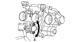
a. Temporary tighten the throttle position sensor.
b. Check that the throttle valves are fully closed.
c. Connect the throttle position sensor to the wire harness.
d. Turn the main switch to "OFF".
e. Simultaneously press and hold the "TCS" button "1" and "RESET" button "2", turn the main switch to "ON", and continue to press the buttons for 8 seconds more.
TIP
"ECU" appears on the multi-function meter right display.
f. Simultaneously press the "TCS" button "1" and "RESET" button "2" for 2 seconds or more.
TIP
"DIAG" appears on the multi-function meter right display.

g. Press the "TCS" button "1" to select the diagnostic mode "DIAG" "3" or the CO adjustment mode "CO".

h. After selecting "DIAG", simultaneously press the "TCS" button "1" and "RESET" button "2" for 2 seconds or more to execute the selection.
TIP
The diagnostic code number "01" appears on the multi-function meter right display.

i. Diagnostic code number "01" is selected.
j. Adjust the position of the throttle position sensor angle so that 11-21 can appear in the meter right display.
k. After adjusting the throttle position sensor angle, tighten the throttle position sensor screws "4".
 Throttle position sensor screw 3.5 Nm (0.35 m*kgf, 2.5 ft*lbf)

Adjusting the accelerator position sensor
WARNING
- Handle the accelerator position sensor with special care.
- Never subject the accelerator position sensor to strong shocks. If the accelerator position sensor is dropped, replace it.
1. Check:
- Accelerator position sensor
2. Adjust:
- Accelerator position sensor angle
TIP
Before adjusting the accelerator position sensor, the throttle bodies must be removed.
a. Temporary tighten the accelerator position sensor.
b. Check that the throttle valves are fully closed.
c. Connect the accelerator position sensor to the wire harness.
d. Connect the throttle cables to the throttle bodies.
e. Turn the main switch to "OFF".
f. Simultaneously press and hold the "TCS" button "1" and "RESET" button "2", turn the main switch to "ON", and continue to press the buttons for 8 seconds more.
TIP
"ECU" appears on the multi-function meter right display.
g. Simultaneously press the "TCS" button "1" and "RESET" button "2" for 2 seconds or more.
TIP
"DIAG" appears on the multi-function meter right display.

h. Press the "TCS" button "1" to select the diagnostic mode "DIAG" "3" or the CO adjustment mode "CO".

i. After selecting "DIAG", simultaneously press the "TCS" button "1" and "RESET" button "2" for 2 seconds or more to execute the selection.
TIP
The diagnostic code number "01" appears on the multi-function meter right display.

j. Diagnostic code number "14" is selected.
k. Turn the throttle grip to the fully closed position.
l. Adjust the position of the accelerator position sensor angle so that 12-22 can appear in the meter.
m. After adjusting the accelerator position sensor angle, tighten the accelerator position sensor screws "4".
 Accelerator position sensor screw 3.5 Nm (0.35 m*kgf, 2.5 ft*lbf)

7-13 display.
h. Press the "TCS" button "1" to select the diagnostic mode "DIAG" "3" or the CO adjustment mode "CO".
i. After selecting "DIAG", simultaneously press the "TCS" button "1" and "RESET" button "2" for 2 seconds or more to execute the selection.
TIP The diagnostic code number "01" appears on the multi-function meter right display.
j. Diagnostic code number "14" is selected.
k. Turn the throttle grip to the fully closed position.
l. Adjust the position of the accelerator position sensor angle so that 12-22 can appear in the meter.
m. After adjusting the accelerator position sensor angle, tighten the accelerator position sensor screws "4".
n. Turn the throttle grip to the fully open position.
o. Check the meter display value. If the meter display value is not 97-107, adjust the accelerator position sensor angle.
p. Select the diagnostic code number "15".
q. Turn the throttle grip to the fully closed position.
r. Check the meter display value. If the meter display value is not 10-24, adjust the accelerator position sensor angle.
s. Turn the throttle grip to the fully open position.
t. Check the meter display value. If the meter display value is not 95-109, adjust the accelerator position sensor angle.
u. Repeat steps (j) to (t) until the meter display values are within the specified ranges.
v. If the meter display values are not within the specified ranges after repeating steps (j) to (t) several times, replace the accelerator position sensor.
See also:
 Yamaha Tracer MT09TRA - Service manual > Installing the fuel pump
1. Install: Fuel pump gasket Fuel pump Fuel pump bracket Fuel pump bolts Fuel pump bolt 4.0 Nm (0.40 m*kgf, 2.9 ft*lbf)
 Yamaha Tracer MT09TRA - Service manual > Air induction system
1. Air filter case 2. Air induction system hose (air filter case to air cut-off valve)

 BMW G310GS
 Honda CBR125RW
 Husqvarna 401 Vitpilen
 KTM 890 Duke R
 Mash Dirt Track 650
 Peugeot Kisbee
 Yamaha Tracer MT-09
 Honda CBR125RW
 Peugeot Kisbee
 Yamaha Tracer MT-09