 Yamaha Tracer MT09TRA - Service manual > Transmission
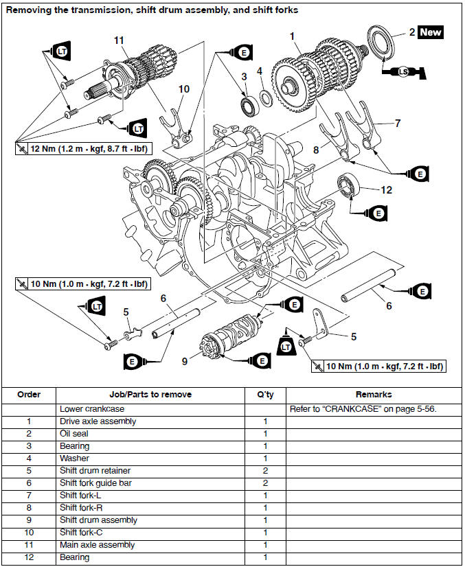
Removing the transmission
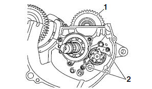
1. Remove:
- Drive axle assembly "1"
- Shift drum retainers "2"
- Shift fork guide bars
- Shift fork-L
- Shift fork-R
- Shift drum assembly
- Shift fork-C
2. Remove:
- Bearing housing "1"
- Main axle assembly "2"
a. Insert two bolts "3" of the proper size, as shown in the illustration, into the main axle assembly bearing housing.
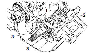
b. Tighten the bolts until they contact the crankcase surface.
c. Continue tightening the bolts until the main axle assembly comes free from the upper crankcase.
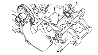
3. Remove
- Bearing "1"
Checking the shift forks
The following procedure applies to all of the shift forks.
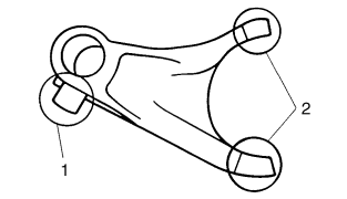
1. Check:
- Shift fork cam follower "1"
- Shift fork pawl "2". Bends/damage/scoring/wear → Replace the shift fork.
2. Check:
- Shift fork guide bar
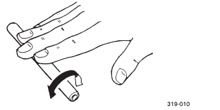
Roll the shift fork guide bar on a flat surface.
Bends → Replace.
WARNING
Do not attempt to straighten a bent shift fork guide bar.
3. Check:
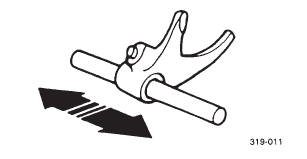
- Shift fork movement (along the shift fork guide bar)
Rough movement → Replace the shift forks and shift fork guide bar as a set.
Checking the shift drum assembly
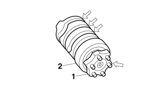
1. Check:
- Shift drum groove Damage/scratches/wear → Replace the shift drum assembly.
- Shift drum segment "1" Damage/wear → Replace the shift drum assembly.
- Shift drum bearing "2" Damage/pitting → Replace the shift drum assembly.
Checking the transmission
1. Measure:
- Main axle runout (with a centering device and dial gauge "1")
Out of specification → Replace the main axle.
 Main axle runout limit 0.08
mm (0.0032 in)

2. Measure:
- Drive axle runout (with a centering device and dial gauge "1")
Out of specification → Replace the drive axle.
 Drive axle runout limit 0.08 mm (0.0032 in)

3. Check:
- Transmission gears.
Blue discoloration/pitting/wear → Replace the defective gear(s).
- Transmission gear dogs.
Cracks/damage/rounded edges → Replace the defective gear(s).

4. Check:
- Transmission gear engagement.
(each pinion gear to its respective wheel gear) Incorrect → Reassemble the transmission axle assemblies.
5. Check:
- Transmission gear movement.
Rough movement → Replace the defective part(s).
6. Check:
- Circlips.
Bends/damage/looseness → Replace.
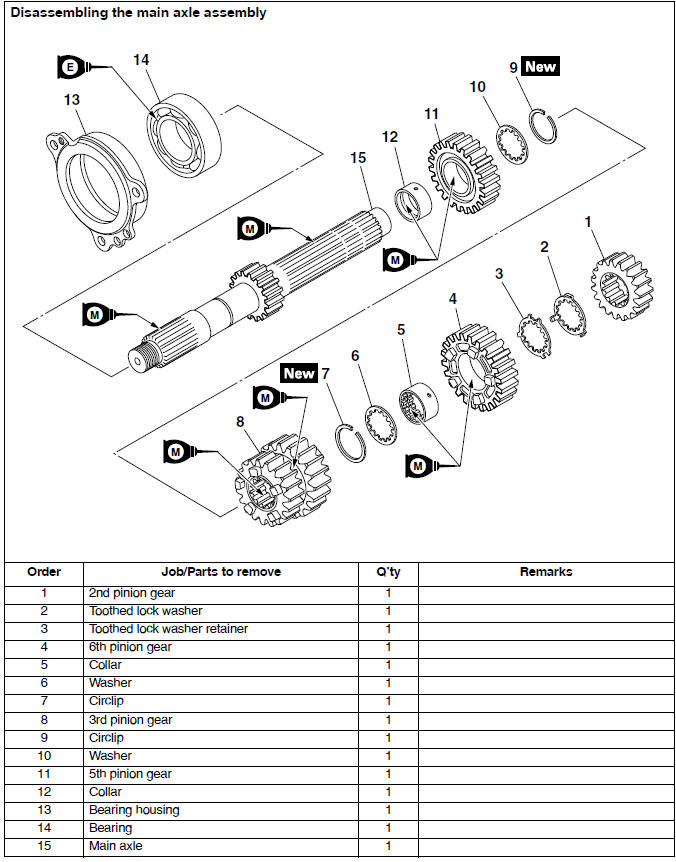
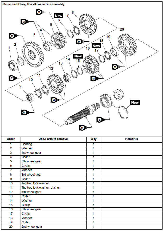
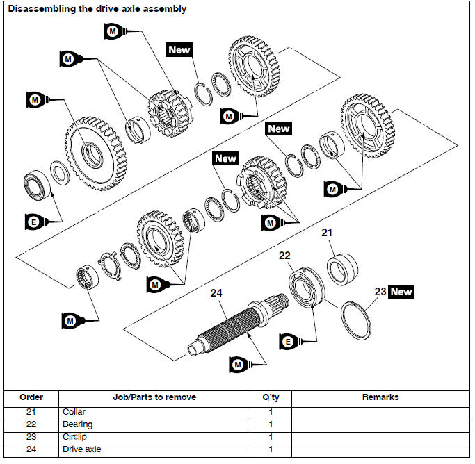
Assembling the main axle and drive axle
1. Install:
- Toothed washer "1"
- Circlip "2"

TIP
- Be sure the circlip sharp-edged corner "a" is positioned opposite side to the toothed washer and gear.
- Align the opening between the ends "b" of the circlip with a groove "c" in the axle.
- Install the circlip so that a spline "d" is in the center of the gap between the circlip ends "e" as shown.

- Main axle
- Drive axle
2. Install:
- Toothed lock washer retainer "1"
- Toothed lock washer "2"
TIP
- With the toothed lock washer retainer in the groove "a" in the axle, align the projection on the retainer with an axle spline, and then install the toothed lock washer.
- Be sure to align the projection on the toothed lock washer that is between the alignment marks "b" with the alignment mark "c" on the retainer.

- Main axle
- Drive axle
Installing the transmission
1. Install:
- Bearing "1"
TIP
Face the seal side of bearing to the outside.
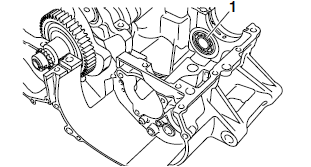
2. Install:
- Main axle assembly "1"
- Bearing housing "2"
 Main axle bearing housing
bolt 12 Nm (1.2 m*kgf, 8.7 ft*lbf) LOCTITE

3. Install:
- Shift fork-C "1"
- Shift drum assembly "2"
- Shift fork guide bar "3"
TIP
- The embossed marks on the shift forks should face towards the right side of the engine and be in the following sequence: "R", "C", "L".
- Carefully position the shift forks so that they are installed correctly into the transmission gears.
- Install shift fork-C into the groove "a" in the 3rd and 4th pinion gear on the main axle.

4. Install:
- Shift fork-R "1"
- Shift fork-L "2"
- Shift fork guide bar
- Shift drum retainers "3"
- Bearing
- Oil seal

- Circlip "4"

- Drive axle assembly "5"
 Shift drum retainer bolt 10 Nm (1.0 m*kgf, 7.2 ft*lbf) LOCTITE
TIP
- Install shift fork-R into the groove "a" in the 5th wheel gear and shift fork-L into the groove "b" in the 6th wheel gear on the drive axle.
- Install the shift drum retainer with its "OUT" mark "c" facing outward.
- Touch the protrusion "d" on the shift fork guide bar to the side of the shift drum retainer.
- Make sure that the drive axle bearing circlip "4" is inserted into the grooves "e" in the upper crankcase.

5. Check:
- Transmission.
Rough movement → Repair.
TIP
Oil each gear, shaft, and bearing thoroughly.
See also:
 Yamaha Tracer MT09TRA - Service manual > Crankshaft and balancer shaft
Removing the crankshaft and balancer shaft 1. Remove: Balancer shaft "1" Balancer shaft journal bearing Crankshaft assembly "2" Crankshaft journal bearings

 BMW G310GS
 Honda CBR125RW
 Husqvarna 401 Vitpilen
 KTM 890 Duke R
 Mash Dirt Track 650
 Peugeot Kisbee
 Yamaha Tracer MT-09
 Honda CBR125RW
 Peugeot Kisbee
 Yamaha Tracer MT-09