 Yamaha Tracer MT09TRA - Service manual > Crankshaft and balancer shaft

Removing the crankshaft and balancer shaft
1. Remove:
- Balancer shaft "1"
- Balancer shaft journal bearing
- Crankshaft assembly "2"
- Crankshaft journal bearings
TIP
Identify the position of each balancer shaft journal bearings and crankshaft journal bearings so that it can be reinstalled in its original place.

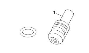
Checking the oil nozzles
The following procedure applies to all of the oil nozzles.
1. Check:
- Oil nozzle "1" Damage/wear → Replace the oil nozzle.
- Oil passage Obstruction → Blow out with compressed air.
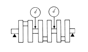
Checking the crankshaft
1. Measure:
- Crankshaft runout
Out of specification → Replace the crankshaft.
 Runout limit 0.030 mm
(0.0012 in)
2. Check:
- Crankshaft journal surfaces
- Crankshaft pin surfaces
- Bearing surfaces
Scratches/wear → Replace the crankshaft.
3. Measure:
- Crankshaft-journal-to-crankshaft-journalbearing clearance
Out of specification → Replace the crankshaft journal bearings.
 Journal oil clearance
0.014-0.038 mm (0.0006-0.0015 in)
NOTICE
Do not interchange the crankshaft journal bearings. To obtain the correct crankshaftjournal- to-crankshaft-journal-bearing clearance and prevent engine damage, the crankshaft journal bearings must be installed in their original positions.
a. Clean the crankshaft journal bearings, crankshaft journals, and bearing portions of the crankcase.
b. Place the upper crankcase upside down on a bench.
c. Install the crankshaft journal upper bearings "1" and the crankshaft into the upper crankcase.
TIP
Align the projections "a" on the crankshaft journal upper bearings with the notches "b" in the upper crankcase.

d. Put a piece of Plastigauge "1" on each crankshaft journal.
TIP
Do not put the Plastigauge over the oil hole in the crankshaft journal.
e. Install the crankshaft journal lower bearings "1" into the lower crankcase and assemble the crankcase halves.
TIP
- Align the projections "a" of the crankshaft journal lower bearings with the notches "b" in the lower crankcase.
- Do not move the crankshaft until the clearance measurement has been completed.

f. Tighten the bolts to specification in the tightening sequence cast on the crankcase.
Refer to "CRANKCASE"
g. Remove the lower crankcase and the crankshaft journal lower bearings.
h. Measure the compressed Plastigauge width "a" on each crankshaft journal.
If the crankshaft-journal-to-crankshaft-journaljournal- bearing clearance is out of specification, select replacement crankshaft journal bearings.
4. Select:
- Crankshaft journal bearings (J1 -J4)
TIP
- The numbers "A" stamped into the crankshaft web and the numbers "B" stamped into the lower crankcase are used to determine the replacement crankshaft journal bearing sizes.
- "J1 "-"J4 " refer to the bearings shown in the crankshaft and lower crankcase illustration.
- If "J1 "-"J4 " are the same, use the same size for all of the bearings.
For example, if the crankcase "J1 " and crankshaft web "J1 " numbers are 7 and 2 respectively, then the bearing size for "J1 " is:
"J1 " (crankcase) - "J1 " (crankshaft web) -1 = 7 - 2 - 1 = 4 (green)
 Bearing color code
0.White 1.Blue 2.Black 3.Brown 4.Green


Checking the balancer shaft
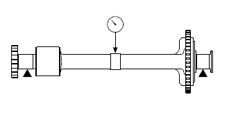
1. Measure:
- Balancer shaft runout
Out of specification → Replace the balancer shaft
 Balancer shaft runout
limit 0.030 mm (0.0012 in)
2. Check:
- Balancer shaft journal surfaces
- Bearing surfaces
Scratches/wear → Replace the balancer shaft.
3. Measure:
Balancer shaft journal-to-balancer shaft journal bearing clearance Out of specification → Replace the balancer shaft journal bearings.
 Balancer shaft journal
to balancer shaft bearing clearance 0.024-0.048 mm (0.0009-0.0019 in)
NOTICE
Do not interchange the balancer shaft journal bearings. To obtain the correct balancer shaft-journal-to-balancer shaft-journal-bearing clearance and prevent engine damage, the balancer shaft journal bearings must be installed in their original positions.
a. Clean the balancer shaft journal bearings, balancer shaft journals, and bearing portions of the crankcase.
b. Place the upper crankcase upside down on a bench.
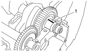
c. Install the balancer shaft journal upper bearings "1" and the balancer shaft into the upper crankcase.
TIP
Align the projections "a" on the balancer shaft journal upper bearings with the notches "b" in the upper crankcase.

d. Put a piece of Plastigauge "1" on each balancer shaft journal.
TIP
Do not put the Plastigauge over the oil hole in the balancer shaft journal.
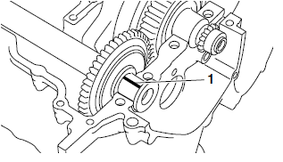
e. Install the balancer shaft journal lower bearings "1" into the lower crankcase and assemble the crankcase halves.
TIP
- Align the projections "a" of the balancer shaft journal lower bearings with the notches "b" in the crankcase.
- Do not move the balancer shaft until the clearance measurement has been completed.

f. Tighten the bolts to specification in the tightening sequence cast on the crankcase. Refer to "CRANKCASE"
g. Remove the lower crankcase and the balancer shaft journal lower bearings.
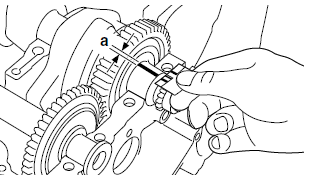
h. Measure the compressed Plastigauge width "a" on each balancer shaft journal. If the balancer shaft-journal-to-balancer shaft-journal- bearing clearance is out of specification, select replacement balancer shaft journal bearings
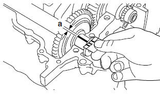
4. Select:
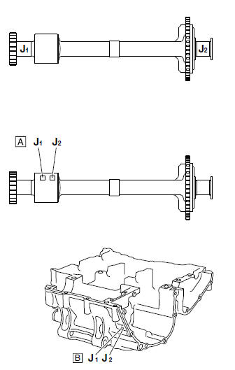
- Balancer shaft journal bearing (J1 -J2)
TIP
- The numbers "A" stamped into the balancer shaft web and the numbers "B" stamped into the lower crankcase are used to determine the replacement balancer shaft journal bearing sizes.
- "J1 "-"J2 " refer to the bearings shown in the balancer shaft and lower crankcase illustration.
- If "J1 "-"J2 " are the same, use the same siz for all of the bearings.
For example, if the crankcase "J1 " and balancer shaft web "J1 " numbers are 5 and 2 respectively, then the bearing size for "J1 " is:
"J1" (crankcase) - "J1 " (balancer shaft web) = 5 - 2 = 3 (brown)
 Bearing color code 1.Blue
2.Black 3.Brown 4.Green 5.Yellow
Installing the crankshaft
1. Install:
- Crankshaft journal upper bearings (into the upper crankcase)
- Crankshaft journal lower bearings (into the lower crankcase)
- Crankshaft
TIP
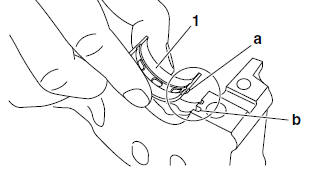
- Align the projections "a" on the crankshaft journal bearings "1" with the notches "b" in the crankcase.
- Be sure to install each crankshaft journal bearings in its original place.
Installing the balancer assembly
1. Install:
- Balancer shaft journal upper bearings (into the upper crankcase)
- Balancer shaft journal lower bearings (into the lower crankcase)
TIP
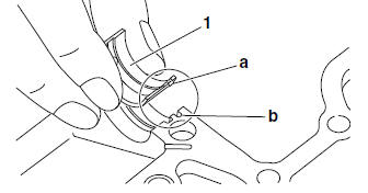
- Align the projections "a" on the balancer shaft journal bearings "1" with the notches "b" in the crankcases.
- Be sure to install each balancer shaft journal bearing in its original place.
2. Install:
- Balancer shaft
TIP
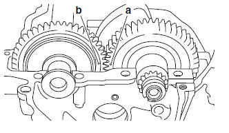
Install by aligning the crankshaft match mark "a" and the balancer shaft match mark "b".
See also:
 Yamaha Tracer MT09TRA - Service manual > Connecting rods and pistons
Removing the connecting rods and pistons The following procedure applies to all of the connecting rods and pistons. Connecting rod cap "1" Connecting rod Big end bearings

 BMW G310GS
 Honda CBR125RW
 Husqvarna 401 Vitpilen
 KTM 890 Duke R
 Mash Dirt Track 650
 Peugeot Kisbee
 Yamaha Tracer MT-09
 Honda CBR125RW
 Peugeot Kisbee
 Yamaha Tracer MT-09