 Yamaha Tracer MT09TRA - Service manual > Abs component functions
Wheel sensors and wheel sensor rotors
Wheel sensors "1" detect the wheel speed and transmit the rotation signal to the ABS ECU.
Each wheel sensor is composed of a permanent magnet and a hall IC. The sensor rotors "2" rotate with the wheels. The sensor rotors "2" have 40 slots and are installed close to the wheel sensors. As the sensor rotor rotates, the hall element in the hall IC installed in the wheel sensor generates pulses. The pulse frequency, which is proportional to the magnetic flux density, is converted into a wave in the hall IC so that it can be output.
The ABS ECU calculates the wheel rotation speed by detecting the pulse frequency.

- At low speed
- At high speed
- Wheel sensor
- Wheel sensor rotor
- Voltage
- Time
ABS warning light
The ABS warning light "1" comes on to warn the rider if a malfunction in the ABS occurs.
When the main switch is turned to "ON", the ABS warning light comes on to check the electrical circuit and the system function (ABS self-diagnosis), and goes off when the vehicle is operated (the function check is properly completed at a speed of about 6 to 10 km/h [3.8 to 6.3 mi/h]).
TIP
After all checks and servicing are completed, the ABS warning light will go off when the vehicle is ridden or pushed at a speed of 7 km/h (4 mi/h) or faster.
NOTICE
If the rear wheel is raced with the vehicle on the centerstand, the ABS warning light may flash or come on. If this occurs, turn the main switch to "OFF", then back to "ON". The ABS operation is normal if the ABS warning light goes off after the vehicle starts off. If the fault codes are not deleted, the ABS warning light goes off after the vehicle is ridden at a speed of approximately 30 km/h (19 mph).

Hydraulic unit assembly
The hydraulic unit assembly "1" is composed of hydraulic control valves (each with a outlet solenoid valve and inlet solenoid valve), buffer chambers, hydraulic pumps, an ABS motor, and ABS ECU. The hydraulic unit adjusts the front and rear wheel brake fluid pressure to control the wheel speed according to signals transmitted from the ABS ECU.

Hydraulic control valve
The hydraulic control valve is composed of a inlet solenoid valve and outlet solenoid valve.
The electromagnetic force generated in the inlet solenoid valve varies proportionally with the duty cycle control voltage that is supplied to it. Since this voltage is continuously variable, the solenoid valve moves smoothly and the hydraulic pressure is adjusted linearly.
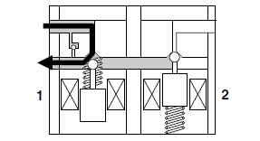
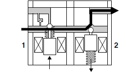
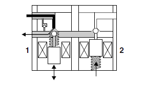
1. When the brakes are operated normally, the inlet solenoid valve "1" is open and the outlet solenoid valve "2" is closed. The brake line between the brake master cylinder and brake caliper is open.

2. When the ABS is activated, the inlet solenoid valve "1" closes and the outlet solenoid valve "2" opens using the power supplied from the ABS ECU signals. This reduces the hydraulic pressure.

3. When the ABS ECU sends a signal to stop reducing the hydraulic pressure, the outlet solenoid valve "2" closes and the brake fluid is pressurized again. The inlet solenoid valve "1" controls the hydraulic pressure difference between the brake fluid in the upper brake lines (brake master cylinder side) and the brake fluid in the lower brake lines (brake caliper side).

Buffer chamber
The buffer chamber accumulates the brake fluid that is depressurized while the ABS is operating.

- Buffer chamber (pressurizing phase)
- Buffer chamber (depressurizing phase)
- Raised piston
ABS ECU
The ABS ECU is integrated with the hydraulic unit to achieve a compact and lightweight design.
As shown in the following block diagram, the ABS ECU receives wheel sensor signals from the front and rear wheels and also receives signals from other monitor circuits.

- Battery
- AC magneto
- Rectifier/regulator
- Main fuse
- ABS motor fuse
- ABS solenoid fuse
- Main switch
- ABS ECU fuse
- Signaling system fuse
- Rear brake light switch
- Front brake light switch
- Tail/brake light
- ABS test coupler
- Hydraulic unit assembly
- ABS ECU
- ABS motor relay
- Solenoid relay
- Front brake outlet solenoid
- Front brake inlet solenoid
- Rear brake outlet solenoid
- Rear brake inlet solenoid
- ABS motor
- Meter assembly
- ABS warning light
- ECU (engine control unit)
- Front wheel sensor
- Rear wheel sensor
The necessary actions are confirmed using the monitor circuit and control signals are transmitted to the hydraulic unit assembly.
ABS control operation
The ABS control operation performed in the ABS ECU is divided into the following two parts.
- Hydraulic control
- Self-diagnosis
When a malfunction is detected in the ABS, a fault code is stored in the memory of the ABS ECU for easy problem identification and troubleshooting.
TIP
- Some types of malfunctions are not recorded in the memory of the ABS ECU (e.g., a blown ABS ECU fuse).
- The ABS performs a self-diagnosis test for a few seconds each time the vehicle first starts off after the main switch was turned on. During this test, a "clicking" noise can be heard from under the seat, and if the brake lever or brake pedal are even slightly applied, a vibration can be felt at the lever and pedal, but these do not indicate a malfunction.

- Software operation flow
- Main switch "ON"
- Initialize
- Self-diagnosis (when static)
- Self-diagnosis (when riding)
- Receive signals
- Control operation
- Depressurize/pressurize
See also:
 Yamaha Tracer MT09TRA - Service manual > Outline of the FI system
The main function of a fuel supply system is to provide fuel to the combustion chamber at the optimum air-fuel ratio in accordance with the engine operating conditions and the atmospheric temperature. In the conventional carburetor system, the air-fuel ratio of the mixture that is supplied to the combustion chamber is created by the volume of the intake air and the fuel that is metered by the jet used in the respective carburetor.
 Yamaha Tracer MT09TRA - Service manual > ABS operation
The ABS hydraulic circuit consists of two systems: the front wheel, and rear wheel. The following describes the system for the front wheel only. Normal braking (ABS not activated)

 BMW G310GS
 Honda CBR125RW
 Husqvarna 401 Vitpilen
 KTM 890 Duke R
 Mash Dirt Track 650
 Peugeot Kisbee
 Yamaha Tracer MT-09
 Honda CBR125RW
 Peugeot Kisbee
 Yamaha Tracer MT-09