 Yamaha Tracer MT09TRA - Service manual > Adjusting the drive chain slack
NOTICE
A drive chain that is too tight will overload the engine and other vital parts, and one that is too loose can skip and damage the swingarm or cause an accident. Therefore, keep the drive chain slack within the specified limits.
1. Stand the vehicle on a level surface.
WARNING
Securely support the vehicle so that there is no danger of it falling over.
TIP
Place the vehicle on the centerstand so that the rear wheel is elevated.
2. Shift the transmission into the neutral position.
3. Check:
- Drive chain slack "a"
Out of specification → Adjust.

 Drive chain slack
5.0-15.0 mm (0.20-0.59 in) Limit 25.0 mm (0.98 in)
NOTICE
Improper drive chain slack will overload the engine as well as other vital parts of the motorcycle and can lead to chain slippage or breakage. If the drive chain slack is more than the specified limit, the chain can damage the frame, swingarm, and other parts. To prevent this from occurring, keep the drive chain slack within the specified limits.
4. Loosen:
- Wheel axle nut "1"
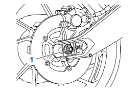
5. Adjust:
- Drive chain slack
a. Loosen both locknuts "1".
b. Turn both adjusting bolts "2" in direction "a" or "b" until the specified drive chain slack is obtained.
Direction "a" Drive chain is tightened.
Direction "b" Drive chain is loosened.

TIP
- To maintain the proper wheel alignment, adjust both sides evenly.
- There should be no clearance between the adjusting block and adjusting bolt.
c. Tighten the wheel axle nut to specification.
 Rear wheel axle nut 150
Nm (15 m*kgf, 108 ft*lbf)
d. Tighten the locknuts to specification.
 Chain puller adjusting
bolt locknut 16 Nm (1.6 m*kgf, 12 ft*lbf)
Lubricating the drive chain
The drive chain consists of many interacting parts. If the drive chain is not maintained properly, it will wear out quickly. Therefore, the drive chain should be serviced, especially when the vehicle is used in dusty areas.
This vehicle has a drive chain with small rubber O-rings between each side plate. Steam cleaning, high-pressure washing, certain solvents, and the use of a coarse brush can damage these O-rings. Therefore, use only kerosene to clean the drive chain. Wipe the drive chain dry and thoroughly lubricate it with engine oil or chain lubricant that is suitable for O-ring chains.
Do not use any other lubricants on the drive chain since they may contain solvents that could damage the O-rings.
 Recommended lubricant
Chain lubricant suitable for Oring chains
Checking and adjusting the steering head
1. Stand the vehicle on a level surface.
WARNING
Securely support the vehicle so that there is no danger of it falling over.
TIP
Place the vehicle on a suitable stand so that the front wheel is elevated.
2. Check:
- Steering head.
Grasp the bottom of the front fork legs and gently rock the front fork.
Blinding/looseness → Adjust the steering head.
3. Remove:
- Upper bracket
4. Adjust:
- Steering head
a. Remove the lock washer "1", the upper ring nut "2", and the rubber washer "3".
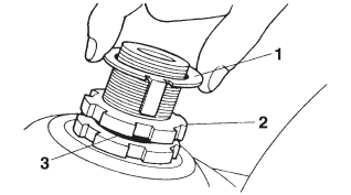
b. Loosen the lower ring nut "4" and then tighten it to specification with a steering nut wrench "5".
TIP
- Set the torque wrench at a right angle to the steering nut wrench.
- Move the steering to the left and right a couple of times to check that it moves smoothly.
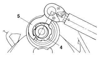
 Steering nut wrench
90890-01403 Exhaust flange nut wrench YU-A9472
 Lower ring nut (initial
tightening torque) 52 Nm (5.2 m*kgf, 38 ft*lbf)
c. Loosen the lower ring nut "6" completely, then tighten it to specification.
WARNING
Do not overtighten the lower ring nut.
 Lower ring nut (final
tightening torque) 18 Nm (1.8 m*kgf, 13 ft*lbf)
d. Check the steering head for looseness or binding by turning the front fork all the way in both directions. If any binding is felt, remove the lower bracket and check the upper and lower bearings.
Refer to "STEERING HEAD"
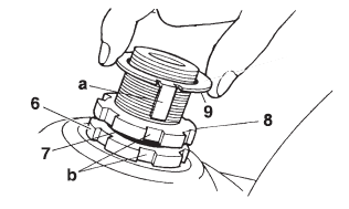
e. Install the rubber washer "7".
f. Install the upper ring nut "8".
g. Finger tighten the upper ring nut, then align the slots of both ring nuts. If necessary, hold the lower ring nut and tighten the upper ring nut until their slots are aligned.
h. Install the lock washer "9".
TIP
Make sure the lock washer tabs "a" sit correctly in the ring nut slots "b".
5. Install:
- Upper bracket
Refer to "HANDLEBAR"
Lubricating the steering head
1. Lubricate:
- Upper bearing
- Lower bearing
- Bearing race
 Recommended lubricant
Lithium-soap-based grease
Checking the chassis fasteners
Make sure that all nuts, bolts, and screws are properly tightened.
Refer to "CHASSIS TIGHTENING TORQUES"
Lubricating the brake lever
Lubricate the pivoting point and metal-to-metal moving parts of the lever.
 Recommended lubricant
Silicone grease
Lubricating the clutch lever
Lubricate the pivoting point and metal-to-metal moving parts of the lever.
 Recommended lubricant
Lithium-soap-based grease
Lubricating the pedal
Lubricate the pivoting point and metal-to-metal moving parts of the pedal.
 Recommended lubricant
Lithium-soap-based grease
Adjusting the shift pedal
The shift pedal position is determined by the installed shift rod length.
1. Measure:
Installed shift rod length "a" Incorrect → Adjust.
 Installed shift rod
length 256.9-258.9 mm (10.11-10.19 in)

2. Adjust:
- Installed shift rod length
a. Loosen both locknuts "1".
b. Turn the shift rod "2" in direction "a" or "b" to obtain the correct shift pedal position.
Direction "a" Installed shift rod length increases.
Direction "b" Installed shift rod length decreases.

c. Tighten both locknuts.
d. Make sure the installed shift rod length is within specification.
Checking the sidestand
1. Check:
- Sidestand operation
Check that the sidestand moves smoothly
Rough movement → Repair or replace.
Lubricating the sidestand
Lubricate the pivoting point, metal-to-metal moving parts and spring contact point of the sidestand.
 Recommended lubricant
Lithium-soap-based grease
Checking the centerstand
1. Check:
- Centerstand operation
Check that the centerstand moves smoothly.
Rough movement → Repair or replace.
Lubricating the centerstand
Lubricate the pivoting point and metal-to-metal moving parts of the centerstand.
 Recommended lubricant
Lithium-soap-based grease
Checking the sidestand switch
Refer to "ELECTRICAL COMPONENTS"
Checking the front fork
1. Stand the vehicle on a level surface.
WARNING
Securely support the vehicle so that there is no danger of it falling over.
2. Check:
- Inner tube Damage/scratches → Replace.
- Front fork leg Oil leaks between inner tube and outer tube → Replace the oil seal.
3. Hold the vehicle upright and apply the front brake.
4. Check:
- Front fork operation
Push down hard on the handlebar several times and check if the front fork rebounds smoothly.
Rough movement → Repair.
Refer to "FRONT FORK"

Adjusting the front fork legs
The following procedure applies to both of the front fork legs.
WARNING
Securely support the vehicle so that there is no danger of it falling over.
Spring preload
WARNING
Always adjust both front fork legs evenly.
Uneven adjustment can result in poor handling and loss of stability.
NOTICE
Never go beyond the maximum or minimum adjustment positions.
1. Adjust:
- Spring preload
a. Turn the adjusting bolt "1" in direction "a" or "b".
Direction "a" Spring preload is increased (suspension is harder).
Direction "b" Spring preload is decreased (suspension is softer).

A. Left side
B. Right side
TIP
The spring preload setting is determined by measuring the distance "c" shown in the illustration.
The shorter distance "c" is, the higher the spring preload; the longer distance "c" is, the lower the spring preload.
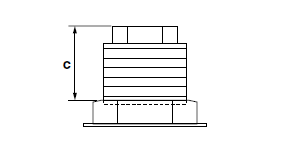
 Spring preload adjusting
positions Minimum 19 mm (0.75 in) Standard 16 mm (0.63 in) Maximum 4 mm (0.16
in)
Rebound damping (right side only)
NOTICE
Never go beyond the maximum or minimum adjustment positions.
1. Adjust:
- Rebound damping
a. Turn the adjusting screw "1" in direction "a" or "b".
Direction "a" Rebound damping is increased (suspension is harder).
Direction "b" Rebound damping is decreased (suspension is softer).
 Rebound damping adjusting
positions Minimum (soft) 11 click(s) in direction "b"* Standard 7 click(s) in
direction "b"* Maximum (hard) 1 click(s) in direction "b"* *With the adjusting
screw fully turned in direction "a"
TIP
Although the total number of clicks of a damping force adjusting mechanism may not exactly match the above specifications due to small differences in production, the actual number of clicks always represents the entire adjusting range. To obtain a precise adjustment, it would be advisable to check the number of clicks of each damping force adjusting mechanism and to modify the specifications as necessary.

Checking the rear shock absorber assembly
Refer to "CHECKING THE REAR SHOCK ABSORBER ASSEMBLY"
Adjusting the rear shock absorber assembly
WARNING
Securely support the vehicle so that there is no danger of it falling over.
Spring preload
NOTICE
Never go beyond the maximum or minimum adjustment positions.
1. Adjust:
- Spring preload
a. Adjust the spring preload with the special wrench "1" and extension bar "2" included in the owner's tool kit.
b. Turn the adjusting ring "3" in direction "a" or "b".
c. Align the desired position on the adjusting ring with the stopper "4".
Direction "a" Spring preload is increased (suspension is harder).
Direction "b" Spring preload is decreased (suspension is softer).
 Spring preload adjusting
positions Minimum 1
Standard 4
Maximum 7

Rebound damping
NOTICE
Never go beyond the maximum or minimum adjustment positions.
1. Adjust:
- Rebound damping
a. Turn the adjusting screw "1" in direction "a" or "b".
Direction "a" Rebound damping is increased (suspension is harder).
Direction "b" Rebound damping is decreased (suspension is softer).
 Rebound damping
adjusting positions Minimum (soft) 3 turn(s) in direction "b"* Standard 1 1/2
turn(s) in direction "b"* Maximum (hard) Adjusting screw fully turned in
direction "a" *With the adjusting screw fully turned in direction "a"
TIP
To obtain a precise adjustment, it is advisable to check the actual total number of turns of the damping force adjusting mechanism. This adjustment range may not exactly match the specifications listed due to small differences in production.

Checking the connecting arm and relay arm
Refer to "CHECKING THE CONNECTING ARM AND RELAY ARM"
Checking the engine oil level
1. Stand the vehicle on a level surface.
TIP
- Place the vehicle on the centerstand.
- Make sure the vehicle is upright
2. Start the engine, warm it up for several minutes, and then turn it off.
3. Check:
- Engine oil level
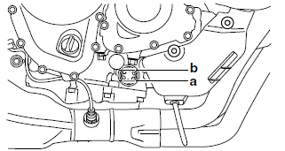
The engine oil level should be between the minimum level mark "a" and maximum level mark "b".
Below the minimum level mark → Add the recommended engine oil to the proper level.
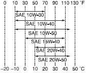
 Recommended brand
YAMALUBE Type SAE 10W-30, 10W-40, 10W-50, 15W-40, 20W-40 or 20W-50 Recommended
engine oil grade API service SG type or higher, JASO standard MA
NOTICE
- Engine oil also lubricates the clutch and the wrong oil types or additives could cause clutch slippage. Therefore, do not add any chemical additives or use engine oils with a grade of "CD" or higher and do not use oils labeled "ENERGY CONSERVING II".
- Do not allow foreign materials to enter the crankcase.
TIP
Before checking the engine oil level, wait a few minutes until the oil has settled
4. Start the engine, warm it up for several minutes, and then turn it off.
5. Check the engine oil level again.
TIP
Before checking the engine oil level, wait a few minutes until the oil has settled.
Changing the engine oil
1. Start the engine, warm it up for several minutes, and then turn it off.
2. Place a container under the engine oil drain bolt.
3. Remove:
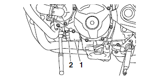
- Engine oil filler cap "1"
- Engine oil drain bolt "2"
- Gasket "3"

A. MT09TRA for Europe: RN29F0011886 and after MT09TRAG for Oceania: RN29K 0000556 and after
4. Drain:
- Engine oil (completely from the crankcase)
5. If the oil filter cartridge is also to be replaced, perform the following procedure.
a. Remove the oil filter cartridge "1" with an oil filter wrench "2".
 Oil filter wrench
90890-01426 Oil filter wrench YU-38411
b. Lubricate the O-ring "3" of the new oil filter cartridge with a thin coat of engine oil.
NOTICE
Make sure the O-ring "3" is positioned correctly in the groove of the oil filter cartridge.
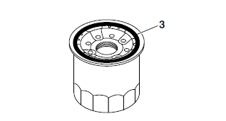
c. Tighten the new oil filter cartridge to specification with an oil filter wrench.
 Oil filter cartridge 17
Nm (1.7 m*kgf, 12 ft*lbf)
6. Install:
- Engine oil drain bolt (along with the gasket
 )
)
 Engine oil drain bolt 43
Nm (4.3 m*kgf, 31 ft*lbf)
7. Fill:
- Crankcase (with the specified amount of the recommended engine oil)
 Engine oil quantity
Quantity (disassembled) 3.40 L (3.59 US qt, 2.99 Imp.qt) Without oil filter
cartridge replacement 2.40 L (2.54 US qt, 2.11 Imp.qt) With oil filter cartridge
replacement 2.70 L (2.85 US qt, 2.38 Imp.qt)
8. Install:
- Engine oil filler cap (along with the O-ring
 )
)
9. Start the engine, warm it up for several minutes, and then turn it off.
10.Check:
- Engine (for engine oil leaks)
11.Check:
- Engine oil level Refer to "CHECKING THE ENGINE OIL LEVEL"
Measuring the engine oil pressure
1. Check:
Engine oil level Below the minimum level mark "a" → Add the recommended engine oil to the proper level.
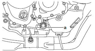
2. Start the engine, warm it up for several minutes, and then turn it off.
NOTICE
When the engine is cold, the engine oil will have a higher viscosity, causing the engine oil pressure to increase. Therefore, be sure to measure the engine oil pressure after warming up the engine.
3. Remove:
- Main gallery bolt "1"
WARNING
The engine, muffler and engine oil are extremely hot.
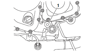
4. Install:
- Oil pressure gauge "1"
- Adapter "2"
 Pressure gauge
90890-03153 Pressure gauge YU-03153 Oil pressure adapter H 90890-03139

5. Measure:
- Engine oil pressure (at the following conditions)
 Oil pressure 230.0 kPa/5000
r/min@100 ºC (2.3 kgf/cm2/5000 r/min, 33.4 psi/5000
r/min@212 ºF)
Out of specification → Check.

6. Install:
- Main gallery bolt
 Main gallery bolt 8 Nm
(0.8 m*kgf, 5.8 ft*lbf)
Checking the coolant level
1. Stand the vehicle on a level surface.
TIP
- Place the vehicle on the centerstand.
- Make sure the vehicle is upright.
2. Check:
- Coolant level
The coolant level should be between the maximum level mark "a" and minimum level mark "b".
Below the minimum level mark → Add the recommended coolant to the proper level.

NOTICE
- Adding water instead of coolant dilutes the antifreeze concentration of the coolant. If water is used instead of coolant; check, and if necessary, correct the antifreeze concentration of the coolant.
- Use only distilled water. However, if distilled water is not available, soft water may be used.
3. Start the engine, warm it up for several minutes, and then turn it off.
4. Check:
- Coolant level
TIP
Before checking the coolant level, wait a few minutes until it settles.
Checking the cooling system
1. Check:
- Radiator "1"
- Radiator inlet hose "2"
- Radiator outlet hose "3"
- Oil cooler "4"
- Oil cooler inlet hose "5"
- Oil cooler outlet hose "6"
- Water jacket joint "7"
- Water pump inlet hose "8"
Cracks/damage → Replace.
Refer to "RADIATOR" "OIL COOLER" , "THERMOSTAT"

Changing the coolant
1. Remove:
- Front side panel (right) Refer to "GENERAL CHASSIS (2)"
- Radiator cap bolt "1"
- Radiator cap "2"
- Radiator cap stopper "3"
WARNING
A hot radiator is under pressure. Therefore, do not remove the radiator cap when the engine is hot. Scalding hot fluid and steam may be blown out, which could cause serious injury.
When the engine has cooled, open the radiator cap as follows: Place a thick rag or a towel over the radiator cap and slowly turn the radiator cap counterclockwise toward the detent to allow any residual pressure to escape. When the hissing sound has stopped, press down on the radiator cap and turn it counterclockwise to remove.

2. Remove:
- Coolant reservoir bolt "1"
- Coolant reservoir cover "2"
- Coolant reservoir "3"
- Collars "4"

3. Remove:
- Coolant reservoir cap "1"
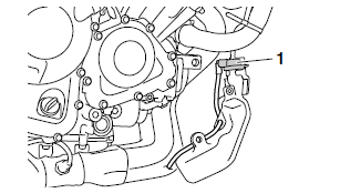
4. Drain:
- Coolant (from the coolant reservoir)
5. Remove:
- Water pump drain bolt "1"
- Copper washer "2"

6. Drain:
- Coolant (from the engine and radiator)
7. Install:
- Water pump drain bolt
- Copper washer

 Water pump drain bolt 10
Nm (1.0 m*kgf, 7.2 ft*lbf)
8. Install:
- Collars
- Coolant reservoir
- Coolant reservoir cover
- Coolant reservoir bolt
 Coolant reservoir bolt
(M5) 0.5 Nm (0.05 m*kgf, 0.36 ft*lbf) Coolant reservoir bolt (M6) 9 Nm (0.9
m*kgf, 6.5 ft*lbf)
9. Fill:
Cooling system (with the specified amount of the recommended coolant)
 Recommended antifreeze
High-quality ethylene glycol antifreeze containing corrosion inhibitors for
aluminum engines Mixing ratio 1:1 (antifreeze: water) Radiator (including all
routes) 1.93 L (2.04 US qt, 1.70 Imp.qt) Coolant reservoir (up to the maximum
level mark) 0.25 L (0.26 US qt, 0.22 Imp.qt)
Handling notes for coolant
Coolant is potentially harmful and should be handled with special care.
WARNING
- If coolant splashes in your eyes, thoroughly wash them with water and consult a doctor.
- If coolant splashes on your clothes, quickly wash it away with water and then with soap and water.
- If coolant is swallowed, induce vomiting and get immediate medical attention.
NOTICE
- Adding water instead of coolant dilutes the antifreeze concentration of the coolant. If water is used instead of coolant; check, and if necessary, correct the antifreeze concentration of the coolant.
- Use only distilled water. However, if distilled water is not available, soft water may be used.
- If coolant comes into contact with painted surfaces, immediately wash them with water.
- Do not mix different types of antifreeze.
10.Install:
- Radiator cap stopper
- Radiator cap
- Radiator cap bolt
 Radiator cap bolt 5 Nm
(0.5 m*kgf, 3.6 ft*lbf)
- Front side panel (right) Refer to "GENERAL CHASSIS (2)"
11.Fill:
- Coolant reservoir (with the recommended coolant to the maximum level mark "a")

12.Install:
- Coolant reservoir cap
13.Start the engine, warm it up for several minutes, and then turn it off.
14.Check:
- Coolant level Refer to "CHECKING THE COOLANT LEVEL"
TIP
Before checking the coolant level, wait a few minutes until the coolant has settled.
Checking the front brake light switch
Refer to "ELECTRICAL COMPONENTS"
Adjusting the rear brake light switch
TIP
The rear brake light switch is operated by movement of the brake pedal. The rear brake light switch is properly adjusted when the brake light comes on just before the braking effect starts.
1. Check:
- Rear brake light operation timing Incorrect → Adjust.
2. Adjust:
- Rear brake light operation timing
a. Hold the main body "1" of the rear brake light switch so that it does not rotate and turn the adjusting nut "2" in direction "a" or "b" until the rear brake light comes on at the proper time.
Direction "a" Brake light comes on sooner.
Direction "b" Brake light comes on later.

Checking and lubricating the cables
The following procedure applies to all of the inner and outer cables.
WARNING
Damaged outer cable may cause the cable to corrode and interfere with its movement. Replace damaged outer cable and inner cables as soon as possible.
1. Check:
- Outer cable
Damage → Replace.
2. Check:
- Cable operation
Rough movement → Lubricate.
 Recommended lubricant
Engine oil or a suitable cable lubricant
TIP
Hold the cable end upright and pour a few drops of lubricant into the cable sheath or use a suitable lubricating device.
Checking the throttle grip
1. Check:
- Throttle cables
Damage/deterioration → Replace.
- Throttle cable installation
Incorrect → Reinstall the throttle cables.
Refer to "HANDLEBAR"
2. Check:
- Throttle grip movement
Rough movement → Lubricate or replace the defective part(s).
 Recommended lubricant
Suitable cable lubricant
TIP
With the engine stopped, turn the throttle grip slowly and release it. Make sure that the throttle grip turns smoothly and returns properly when released.
Repeat this check with the handlebar turned all the way to the left and right.
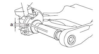
3. Check:
- Throttle grip free play "a"
Out of specification → Adjust.
 Throttle grip free play
3.0-5.0 mm (0.12-0.20 in)
4. Adjust:
- Throttle grip free play
TIP
Prior to adjusting the throttle grip free play, throttle body synchronization should be adjusted properly.
a. Slide back the rubber cover "1".
b. Loosen the locknut "2".
c. Turn the adjusting nut "3" in direction "a" or "b" until the specified throttle grip free play is obtained.
Direction "a" Throttle grip free play is increased.
Direction "b" Throttle grip free play is decreased.

d. Tighten the locknut.
e. Slide the rubber cover to its original position.
TIP
Make sure that the adjusting nut is covered completely by the rubber cover.
Checking and charging the battery
Refer to "CHECKING AND CHARGING THE BATTERY"
Checking the fuses
Refer to "CHECKING THE FUSES"
Adjusting the headlight beams
1. Adjust:
- Headlight beam (vertically)
a. Turn the adjusting knobs "1" in direction "a" or "b".
Direction "a" Headlight beam is lowered.
Direction "b" Headlight beam is raised.

2. Adjust:
- Headlight beam (horizontally)
a. Turn the adjusting screws "1" in direction "a" or "b".
Left headlight
Direction "a" Headlight beam moves to the right.
Direction "b" Headlight beam moves to the left.
Right headlight
Direction "a" Headlight beam moves to the left.
Direction "b" Headlight beam moves to the right.

See also:
 Yamaha Tracer MT09TRA - Service manual > Checking the rear brake pads
The following procedure applies to all of the brake pads. 1. Operate the brake. 2. Check: Rear brake pad Wear indicator grooves "1" almost disappeared → Replace the brake pads as a set.

 BMW G310GS
 Honda CBR125RW
 Husqvarna 401 Vitpilen
 KTM 890 Duke R
 Mash Dirt Track 650
 Peugeot Kisbee
 Yamaha Tracer MT-09
 Honda CBR125RW
 Peugeot Kisbee
 Yamaha Tracer MT-09