 Yamaha Tracer MT09TRA - Service manual > Checking the rear brake pads
The following procedure applies to all of the brake pads.
1. Operate the brake.
2. Check:
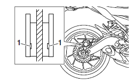
- Rear brake pad
Wear indicator grooves "1" almost disappeared → Replace the brake pads as a set.
Refer to "REAR BRAKE"

Bleeding the hydraulic brake system (ABS)
WARNING
Always bleed the brake system when the brake related parts are removed.
NOTICE
- Bleed the brake system in the following order.
- 1st step: Front brake calipers
- 2nd step: Rear brake caliper
WARNING
Bleed the ABS whenever:
- the system is disassembled.
- a brake hose is loosened, disconnected or replaced.
- the brake fluid level is very low.
- brake operation is faulty.
TIP
- Be careful not to spill any brake fluid or allow the brake master cylinder reservoir or brake fluid reservoir to overflow.
- When bleeding the ABS, make sure that there is always enough brake fluid before applying the brake. Ignoring this precaution could allow air to enter the ABS, considerably lengthening the bleeding procedure.
- If bleeding is difficult, it may be necessary to let the brake fluid settle for a few hours.
- Repeat the bleeding procedure when the tiny bubbles in the hose have disappeared.
1. Bleed:
- ABS
a. Fill the brake master cylinder reservoir or brake fluid reservoir to the proper level with the specified brake fluid.
b. Install the diaphragm (brake master cylinder reservoir or brake fluid reservoir).
c. Connect a clear plastic hose "1" tightly to the bleed screw "2".


A. Front
B. Rear
d. Place the other end of the hose into a container.
e. Slowly apply the brake several times.
f. Fully squeeze the brake lever or fully depress the brake pedal and hold it in position.
g. Loosen the bleed screw.
TIP
Loosening the bleed screw will release the pressure and cause the brake lever to contact the throttle grip or the brake pedal to fully extend.
h. Tighten the bleed screw and then release the brake lever or brake pedal.
i. Repeat steps (e) to (h) until all of the air bubbles have disappeared from the brake fluid in the plastic hose.
j. Check the operation of the hydraulic unit.
Refer to "HYDRAULIC UNIT OPERATION TESTS"
NOTICE
Make sure that the main switch is turned to "OFF" before checking the operation of the hydraulic unit.
k. After operating the ABS, repeat steps (e) to (i) , and then fill the brake master cylinder reservoir or brake fluid reservoir to the proper level with the specified brake fluid.
l. Tighten the bleed screw to specification.
 Brake caliper bleed
screw 5 Nm (0.5 m*kgf, 3.6 ft*lbf)
m. Fill the brake master cylinder reservoir or brake fluid reservoir to the proper level with the specified brake fluid.
Refer to "CHECKING THE BRAKE FLUID LEVEL"
WARNING
After bleeding the hydraulic brake system, check the brake operation.
Checking the front brake hoses
The following procedure applies to all of the brake hoses and brake hose holders.
1. Check:
- Brake hose.
Cracks/damage/wear → Replace.
2. Check:
- Brake hose holder.
Loose → Tighten the holder bolt.
3. Hold the vehicle upright and apply the brake several times.
4. Check:
- Brake hose.
Brake fluid leakage → Replace the damaged hose.
Checking the rear brake hose
1. Check:
Brake hose. Cracks/damage/wear → Replace.
2. Check:
Brake hose holder.
Loose Connection → Tighten the holder bolt.
3. Hold the vehicle upright and apply the rear brake several times.
4. Check:
Brake hose.
Brake fluid leakage → Replace the damaged hose.
Checking the wheels
The following procedure applies to both of the wheels
1. Check:
- Wheel Damage/out-of-round → Replace.
WARNING
Never attempt to make any repairs to the wheel.
TIP
After a tire or wheel has been changed or replaced, always balance the wheel.
Checking the tires
The following procedure applies to both of the tires.
1. Check:
Tire pressure. Out of specification → Regulate.

WARNING
- The tire pressure should only be checked and regulated when the tire temperature equals the ambient air temperature.
- The tire pressure and the suspension must be adjusted according to the total weight (including cargo, rider, passenger and accessories) and the anticipated riding speed.
- Operation of an overloaded vehicle could cause tire
damage, an accident or an injury.
NEVER OVERLOAD THE VEHICLE.
 Tire air pressure
(measured on cold tires)
Loading condition 0-90 kg (0-198 lb)
Front 250 kPa (2.50 kgf/cm2, 36 psi)
Rear 290 kPa (2.90 kgf/cm2, 42 psi)
Loading condition 90-180 kg (198-397 lb)
Front 250 kPa (2.50 kgf/cm2, 36 psi)
Rear 290 kPa (2.90 kgf/cm2, 42 psi)
High-speed riding
Front 250 kPa (2.50 kgf/cm2, 36 psi)
Rear 290 kPa (2.90 kgf/cm2, 42 psi)
Maximum load 180 kg (397 lb)
*Total weight of rider, passenger, cargo and accessories
2. Check:
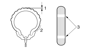
- Tire surfaces
Damage/wear → Replace the tire.
WARNING
It is dangerous to ride with a worn-out tire.
When the tire tread reaches the wear limit, replace the tire immediately.

1. Tire tread depth
2. Side wall
3. Wear indicator
 Wear limit (front)
MT09TRA 1.6 mm (0.06 in)
MT09TRAF 1.5 mm (0.06 in)
Wear limit (rear)
MT09TRA 1.6 mm (0.06 in)
MT09TRAF 1.5 mm (0.06 in)
WARNING
After extensive tests, the tires listed below have been approved by Yamaha Motor Co., Ltd. for this model. The front and rear tires should always be by the same manufacturer and of the same design. No guarantee concerning handling characteristics can be given if a tire combination other than one approved by Yamaha is used on this vehicle.
 Front tire Size 120/70
ZR17M/C (58W) Manufacturer/model DUNLOP/D222F
 Rear tire Size 180/55
ZR17M/C (73W) Manufacturer/model DUNLOP/D222
WARNING
New tires have a relatively low grip on the road surface until they have been slightly worn. Therefore, approximately 100 km should be traveled at normal speed before any high-speed riding is done.
TIP
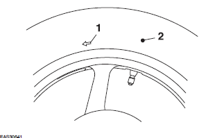
For tires with a direction of rotation mark "1":
- Install the tire with the mark pointing in the direction of wheel rotation.
- Align the mark "2" with the valve installation point.

Checking the wheel bearings
The following procedure applies to all of the wheel bearings.
1. Check:
- Wheel bearings
Refer to "CHECKING THE FRONT WHEEL" and "CHECKING THE REAR WHEEL"
Checking the swingarm operation
1. Check:
- Swingarm operation
Swingarm not working properly → Check the swingarm.
Refer to "SWINGARM"
2. Check:
- Swingarm excessive play Refer to "SWINGARM"
Lubricating the swingarm pivot
1. Lubricate:
- Oil seals
- Collars
 Recommended lubricant
Lithium-soap-based grease
Refer to "INSTALLING THE SWINGARM"
See also:
 Yamaha Tracer MT09TRA - Service manual > Synchronizing the throttle bodies
TIP Before synchronizing the throttle bodies, check the following items: Valve clearance Spark plugs Air filter element Throttle body joints Fuel hose Exhaust system Breather hoses
 Yamaha Tracer MT09TRA - Service manual > Adjusting the drive chain slack
NOTICE A drive chain that is too tight will overload the engine and other vital parts, and one that is too loose can skip and damage the swingarm or cause an accident. Therefore, keep the drive chain slack within the specified limits.

 BMW G310GS
 Honda CBR125RW
 Husqvarna 401 Vitpilen
 KTM 890 Duke R
 Mash Dirt Track 650
 Peugeot Kisbee
 Yamaha Tracer MT-09
 Honda CBR125RW
 Peugeot Kisbee
 Yamaha Tracer MT-09