 Yamaha Tracer MT09TRA - Service manual > Synchronizing the throttle bodies
TIP
Before synchronizing the throttle bodies, check the following items:
- Valve clearance
- Spark plugs
- Air filter element
- Throttle body joints
- Fuel hose
- Exhaust system
- Breather hoses
Checking the throttle body synchronization
1. Stand the vehicle on a level surface.
TIP
Place the vehicle on the centerstand.
2. Remove:
- Fuel tank front cover/Front side panel/Front side cowling Refer to "GENERAL CHASSIS (2)"
- Passenger seat/Rider seat Refer to "GENERAL CHASSIS (1)"
- Fuel tank cover Refer to "GENERAL CHASSIS (3)"
- Fuel tank Refer to "FUEL TANK"
Air filter case Refer to "GENERAL CHASSIS (3)"
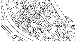
3. Remove:
- Caps "1"

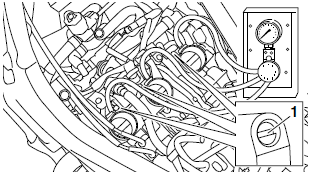
4. Install:
- Vacuum gauge "1"
 Vacuum gauge 90890-03094
Vacuummate YU-44456

5. Install:
- Air filter case Refer to "GENERAL CHASSIS (3)"
- Fuel tank Refer to "FUEL TANK"
6. Check:
- Throttle body synchronization
a. Start the engine, warm it up for several minutes, and then let it run at the specified engine idling speed.
 Engine idling speed
1100-1300 r/min
b. Check the vacuum pressure.
 The difference in vacuum
pressure between the throttle bodies should not exceed 1.33 kPa (10 mmHg).
If out of specification → Adjust the throttle body synchronization.
Adjusting the throttle body synchronization
1. Adjust:
- Throttle body synchronization
a. Start the engine, warm it up for several minutes, and then let it run at the specified engine idling speed.
 Engine idling speed
1100-1300 r/min
b. Using the throttle body that has the bypass air screw "1" with a white paint mark as the standard, adjust the other throttle bodies by turning its bypass air screw in or out.
NOTICE
Do not turn the bypass air screw (white paint mark) of the throttle body that is the stanstandard.
Otherwise, the engine may run roughly at idle and the throttle bodies may not operate properly.
TIP
- Turn the bypass air screw using the carburetor angle driver.
- After each step, rev the engine two or three times, each time for less than a second, and check the synchronization again.
- If a bypass air screw was removed, turn the screw in fully and be sure to synchronize the throttle bodies.
- If the throttle body synchronization can not be adjusted using the bypass air screw, clean or replace the throttle bodies.
- The difference in vacuum pressure between the throttle bodies should not exceed 1.33 kPa (10 mmHg).
 Carburetor angle driver
2 90890-03173

2. Stop the engine and remove the measuring equipment.
3. Install:
- Caps
4. Install:
- Air filter case Refer to "GENERAL CHASSIS (3)"
- Fuel tank Refer to "FUEL TANK"
- Fuel tank cover Refer to "GENERAL CHASSIS (3)"
- Rider seat/Passenger seat Refer to "GENERAL CHASSIS (1)"
- Front side cowling/Front side panel/Fuel tank front cover Refer to "GENERAL CHASSIS (2)"
5. Adjust:
- Throttle grip free play Refer to "CHECKING THE THROTTLE GRIP"
 Throttle grip free play
3.0-5.0 mm (0.12-0.20 in)
Checking the throttle body joints
1. Remove:
- Throttle bodies Refer to "THROTTLE BODIES"
2. Check:
Throttle body joints "1" Cracks/damage → Replace.

3. Install:
- Throttle bodies Refer to "THROTTLE BODIES"
Adjusting the exhaust gas volume
TIP
Be sure to set the CO density level to standard, and then adjust the exhaust gas volume.
1. Turn the main switch to "OFF".
2. Simultaneously press and hold the "TCS" button "1" and "RESET" button "2", turn the main switch to "ON", and continue to press the buttons for 8 seconds or more.
TIP
"ECU" appears on the multi-function meter right display.
3. Simultaneously press the "TCS" button "1" and "RESET" button "2" for 2 seconds or more.
TIP
"DIAG" appears on the multi-function meter right display.

4. Press the "TCS" button "1" to select the CO adjustment mode "CO" "2" or the diagnostic mode "DIAG".

5. After selecting "CO", simultaneously press the "TCS" button "1" and "RESET" button "2" for 2 seconds or more to execute the selection.
6. Press the "TCS" button or "RESET" button to select a cylinder number "3".

TIP
The selected cylinder number appears on the multi-function meter right display.
- To decrease the selected cylinder number, press the "RESET" button.
- To increase the selected cylinder number, press the "TCS" button.
7. After selecting the cylinder number, simultaneously press the "TCS" button "1" and "RESET" button "2" for 2 seconds or more to execute the selection.
8. Change the CO adjustment volume "3" by pressing the "TCS" button or "RESET" button.

TIP
The CO adjustment volume appears on the multi-function meter right display.
- To decrease the CO adjustment volume, press the "RESET" button.
- To increase the CO adjustment volume, press the "TCS" button.
9. Simultaneously press the "TCS" button and "RESET" button to return to the cylinder number selection (step 6).
10.Turn the main switch to "OFF" to cancel the mode.
Checking the air induction system
Refer to "CHECKING THE AIR INDUCTION SYSTEM"
Checking the cylinder head breather hose
1. Remove:
- Air filter case Refer to "GENERAL CHASSIS (3)"
2. Check:
- Cylinder head breather hose "1"
Cracks/damage → Replace.
Loose connection → Connect properly.
NOTICE
Make sure the cylinder head breather hose is routed correctly.

3. Install:
- Air filter case Refer to "GENERAL CHASSIS (3)"
Replacing the air filter element
1. Remove:
- Fuel tank front cover/Front side panel/Front side cowling Refer to "GENERAL CHASSIS (2)"
- Passenger seat/Rider seat Refer to "GENERAL CHASSIS (1)"
- Fuel tank cover Refer to "GENERAL CHASSIS (3)"
- Fuel tank Refer to "FUEL TANK"
2. Remove:
- ECU (engine control unit) "1"
- Air filter case cover "2" Refer to "GENERAL CHASSIS (3)"

3. Check:
- Air filter element "1"
- Air filter seal
Damage → Replace.
TIP
- Replace the air filter element every 40000 km (24000 mi) of operation.
- The air filter needs more frequent service if you are riding in unusually wet or dusty areas.

4. Install:
- Air filter element
- Air filter case cover
- ECU (engine control unit)
NOTICE
Never operate the engine without the air filter element installed. Unfiltered air will cause rapid wear of engine parts and may damage the engine. Operating the engine without the air filter element will also affect throttle body synchronization, leading to poor engine performance and possible overheating.
TIP
When installing the air filter element into the air filter case cover, make sure that the sealing surfaces are aligned to prevent any air leaks.
5. Install:
- Fuel tank Refer to "FUEL TANK"
- Fuel tank cover Refer to "GENERAL CHASSIS (3)"
- Rider seat/Passenger seat Refer to "GENERAL CHASSIS (1)"
- Front side cowling/Front side panel/Fuel tank front cover Refer to "GENERAL CHASSIS (2)"
Adjusting the clutch lever free play
1. Check:
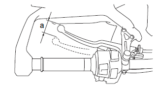
Clutch lever free play "a" Out of specification → Adjust.
 Clutch lever free
play 10.0-15.0 mm (0.39-0.59 in)

2. Adjust:
- Clutch lever free play
Handlebar side
a. Turn the adjusting bolt "1" in direction "a" or "b" until the specified clutch lever free play is obtained.
Direction "a" Clutch lever free play is increased.
Direction "b" Clutch lever free play is decreased.

TIP
If the specified clutch lever free play cannot be obtained on the handlebar side of the cable, use the adjusting nut on the engine side.
Engine side
a. Loosen the locknut "1".
b. Turn the adjusting nut "2" in direction "a" or "b" until the specified clutch lever free play is obtained.
Direction "a" Clutch lever free play is increased.
Direction "b" Clutch lever free play is decreased.
c. Tighten the locknut "1".
 Clutch cable locknut 7
Nm (0.7 m*kgf, 5.1 ft*lbf)

Checking the brake operation
1. Check:
- Brake operation
Brake not working properly → Check the brake system.
Refer to "FRONT BRAKE" and "REAR BRAKE"
TIP
Drive on the dry road, operate the front and rear brakes separately and check to see if the brakes are operating properly.
Checking the brake fluid level
1. Stand the vehicle on a level surface.
TIP
- Place the vehicle on the centerstand.
- Make sure the vehicle is upright.
2. Check:
- Brake fluid level
Below the minimum level mark "a" → Add the specified brake fluid to the proper level.
 Front brake
Specified brake fluid DOT 4
Rear brake
Specified brake fluid DOT 4

A. Front brake
B. Rear brake
WARNING
- Use only the designated brake fluid. Other brake fluids may cause the rubber seals to deteriorate, causing leakage and poor brake performance.
- Refill with the same type of brake fluid that is already in the system. Mixing brake fluids may result in a harmful chemical reaction, leading to poor brake performance.
- When refilling, be careful that water does not enter the brake fluid reservoir. Water will significantly lower the boiling point of the brake fluid and could cause vapor lock.
NOTICE
Brake fluid may damage painted surfaces and plastic parts. Therefore, always clean up any spilt brake fluid immediately.
TIP
In order to ensure a correct reading of the brake fluid level, make sure the top of the brake fluid reservoir is horizontal.
Adjusting the front disc brake
1. Adjust:
- Brake lever position (distance "a" from the throttle grip to the brake lever)
TIP
- While pushing the brake lever forward, turn the adjusting dial "1" until the brake lever is in the desired position.
- Be sure to align the setting on the adjusting dial with the arrow mark "2" on the brake lever holder.
Position #1 Distance "a" is the largest.
Position #5 Distance "a" is the smallest.

WARNING
- After adjusting the brake lever position, make sure the pin on the brake lever holder is firmly inserted in the hole in the adjusting dial.
- A soft or spongy feeling in the brake lever can indicate
the presence of air in the brake system. Before the vehicle is operated, the
air must be removed by bleeding the brake system. Air in the brake system
will considerably reduce brake performance resulting in loss of control and
possibly cause an accident.
Therefore, check and if necessary, bleed the brake system
.
NOTICE
After adjusting the brake lever position, make sure there is no brake drag.
Checking the front brake pads
The following procedure applies to all of the brake pads.
1. Operate the brake.
2. Check:
- Front brake pad
Wear indicators "1" almost touch the brake disc → Replace the brake pads as a set.
Refer to "FRONT BRAKE"
Adjusting the rear disc brake

1. Adjust:
- Brake pedal position
a. Loosen the locknut "1".
b. Turn the adjusting bolt "2" in direction "a" or "b" until the specified brake pedal position is obtained.
Direction "a" Brake pedal is raised.
Direction "b" Brake pedal is lowered.
WARNING
After adjusting the brake pedal position, check that the end of the adjusting bolt "c" is visible through the hole "d".
c. Tighten the locknut "1" to specification.
 Rear brake master
cylinder lock nut 18 Nm (1.8 m*kgf, 13 ft*lbf)
WARNING
A soft or spongy feeling in the brake pedal can indicate the presence of air in the brake system. Before the vehicle is operated, the air must be removed by bleeding the brake system. Air in the brake system will considerably reduce braking performance.
NOTICE
After adjusting the brake pedal position, make sure there is no brake drag.

2. Adjust:
Rear brake light switch.
Refer to "ADJUSTING THE REAR BRAKE LIGHT SWITCH"
See also:
 Yamaha Tracer MT09TRA - Service manual > Adjusting the valve clearance
The following procedure applies to all of the valves. TIP Valve clearance adjustment should be made on a cold engine, at room temperature. 1. Remove: Fuel tank front cover/Front side panel/Front side cowling. Refer to "GENERAL CHASSIS (2)" Passenger seat/Rider seat Refer to "GENERAL CHASSIS (1)" Fuel tank cover Refer to "GENERAL CHASSIS (3)" Fuel tank Refer to "FUEL TANK" Air filter case Refer to "GENERAL CHASSIS (3)" Air cut-off valve Refer to "AIR INDUCTION SYSTEM" Radiator.
 Yamaha Tracer MT09TRA - Service manual > Checking the rear brake pads
The following procedure applies to all of the brake pads. 1. Operate the brake. 2. Check: Rear brake pad Wear indicator grooves "1" almost disappeared → Replace the brake pads as a set.

 BMW G310GS
 Honda CBR125RW
 Husqvarna 401 Vitpilen
 KTM 890 Duke R
 Mash Dirt Track 650
 Peugeot Kisbee
 Yamaha Tracer MT-09
 Honda CBR125RW
 Peugeot Kisbee
 Yamaha Tracer MT-09