 Honda CBR125RW - Service manual > Brake Fluid Replacement/ Air Bleeding
BRAKE FLUID DRAINING
FRONT BRAKE:
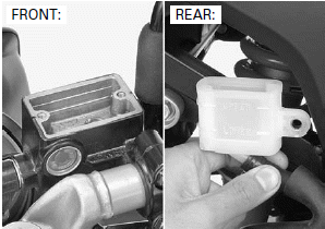
Turn the handlebar until the reservoir is parallel to the ground.
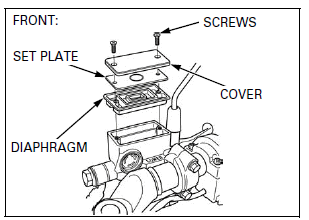
Remove the reservoir cover screws, reservoir cover, set plate and diaphragm.
REAR BRAKE:
Support the motorcycle in an upright position.
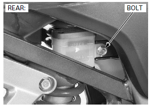
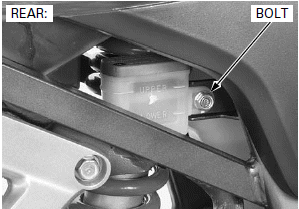
Remove the bolt and reservoir.
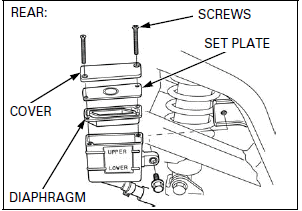
Remove the reservoir cover screws, reservoir cover, set plate and diaphragm.
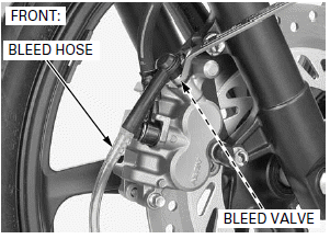
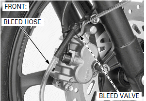
Connect a bleed hose to the caliper bleed valve.
Loosen the bleed valve and pump the brake lever/ pedal until no more fluid flows out of the bleed valve.
BRAKE FLUID FILLING/AIR BLEEDING
Do not mix different types of fluid. They are not compatible.
Fill the reservoir with DOT 3 or DOT 4 brake fluid from a sealed container.
Connect a automatic refill system to the reservoir.
If an automatic refill system is not used, add fluid when the fluid level in the reservoir is low.
NOTE:
Check the fluid level often while bleeding the brake to prevent air from being pumped into the system.
NOTE:
When using a brake bleeding tool, follow the manufacturer's operating instructions.
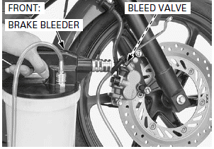
Connect a commercially available brake bleeder to the bleed valve.
Operate the brake bleeder and loosen the bleed valve.
If air enters the bleeder from around the bleed valve threads, seal the threads with teflon tape.
Perform the bleeding procedure until the system is completely flushed/bled.
Close the bleed valve and operate the brake lever/ pedal. If it still feels spongy, bleed the system again.
After bleeding the system completely, tighten the brake caliper bleed valve to the specified torque.
TORQUE: 5.4 N-m (0.6 kgf-m, 4.0 lbf-ft)
If the brake bleeder is not available, perform the following procedure.
Pump up the system pressure with the brake lever/ pedal until the lever/pedal resistance is felt.
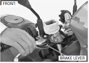
Connect a bleed hose to the bleed valve.
1. Squeeze the brake lever/pedal all the way and loosen the bleed valve 1/2 turn. Wait several seconds and then close the bleed valve.
NOTE:
- Do not release the brake lever/pedal until the bleed valve has been closed.
2. Release the brake lever/pedal slowly and wait several seconds after it reaches the end of its travel.
3. Repeat the steps 1 and 2 until there are no air bubbles in the bleed hose.
After bleeding the system completely, tighten the brake caliper bleed valve to the specified torque.
TORQUE: 5.4 N-m (0.6 kgf-m, 4.0 lbf-ft)
Do not mix different types of fluid. They are not compatible.
Add the reservoir with DOT 3 or DOT 4 brake fluid to the casting ledge/upper level line.
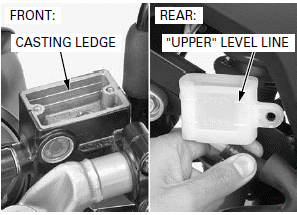
FRONT BRAKE:
Install the diaphragm, set plate, reservoir cover and reservoir cover screws, then tighten the screws to the specified torque.
TORQUE: 1.5 N-m (0.2 kgf-m, 1.1 lbf-ft)
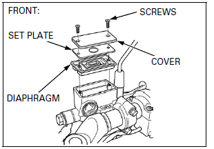
REAR BRAKE:
Install the diaphragm, set plate, reservoir cover and reservoir cover screws, then tighten the screws to the specified torque.
TORQUE: 1.5 N-m (0.2 kgf-m, 1.1 lbf-ft)
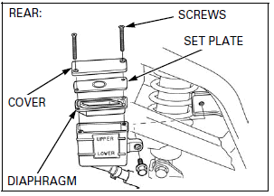
Install the reservoir and bolt.
BRAKE PAD/DISC
FRONT BRAKE PAD REPLACEMENT
Always replace the brake pads in pairs to assure even disc pressure.
Push the caliper pistons all the way in to allow installation of new brake pads.
NOTE:
Check the brake fluid level in the brake master cylinder reservoir as this operation causes the level to rise.
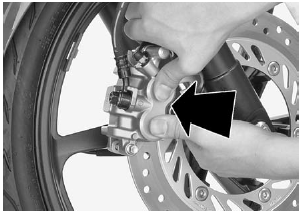
Do not operate the brake lever after removing the brake pads.
Remove the brake pad hanger pin and brake pads.
Check that the O-ring is in good condition, replace if necessary.
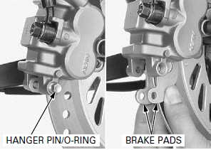
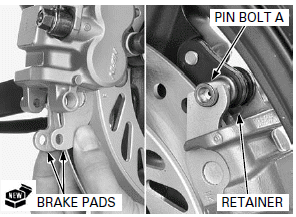
Install new brake pads to the brake caliper so their ends seat against the retainer and brake caliper pin bolt A.
NOTE:
Make sure that the retainer is installed to the brake caliper.
Apply silicone grease to the brake pad hanger pin O-ring and install it to the hanger pin groove.
Install the brake pad hanger pin by pushing the pads against the pad spring to align the hanger pin holes in the pads and brake caliper.
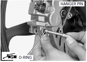
Tighten the brake pad hanger pin to the specified torque.
TORQUE: 17 N-m (1.7 kgf-m, 13 lbf-ft)
Operate the brake lever to seat the caliper pistons against the pads.
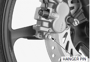
REAR BRAKE PAD REPLACEMENT
Always replace the brake pads in pairs to assure even disc pressure.
Push the caliper pistons all the way in to allow installation of new brake pads.
NOTE:
Check the brake fluid level in the brake master cylinder reservoir as this operation causes the level to rise.
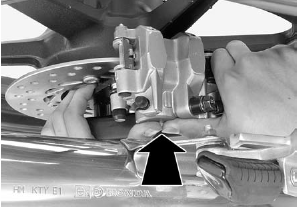
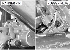
Remove the rubber plug.
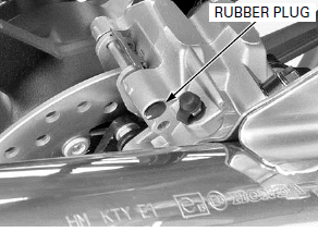
Do not operate the brake pedal after removing the brake pads.
Remove the brake pad hanger pin and brake pads.
Check that the O-ring is in good condition, replace it if necessary.
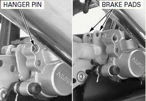
Install new brake pads to the brake caliper so their ends seat against the retainer and brake caliper pin bolt A.
NOTE:
Make sure that the retainer is installed to the brake caliper.
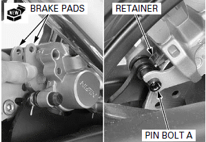
Apply silicone grease to the brake pad hanger pin O-ring and install it to the pad pin groove.
Install the brake pad hanger pin by pushing the pads against the pad spring to align the hanger pin holes in the pads and brake caliper.
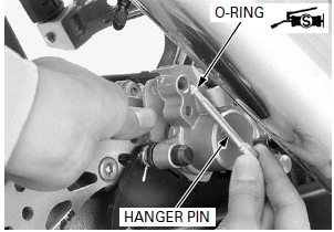
Tighten the brake pad hanger pin to the specified torque.
TORQUE: 17 N-m (1.7 kgf-m, 13 lbf-ft)
Install the rubber plug.
Operate the brake pedal to seat the caliper pistons against the pads.
BRAKE DISC INSPECTION
Visually inspect the brake discs for damage or crack.
Measure the brake disc thickness using a micrometer.
SERVICE LIMITS:
FRONT: 3.5 mm (0.14 in)
REAR: 3.5 mm (0.14 in)
Replace the brake disc if the smallest measurement is less than the service limit.
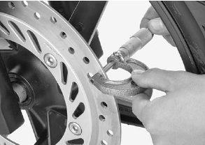
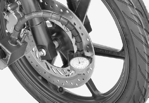
Measure the brake discs warpage using a dial indicator.
SERVICE LIMITS:
FRONT: 0.10 mm (0.004 in)
REAR: 0.10 mm (0.004 in)
Check the wheel bearings for excessive play, if the warpage exceeds the service limit.
Replace the brake disc if the wheel bearings are normal.
See also:
 Honda CBR125RW - Service manual > Hydraulic Brake
COMPONENT LOCATION
 Honda CBR125RW - Service manual > Front/Rear Master Cylinder
FRONT MASTER CYLINDER REMOVAL Drain the brake fluid from the hydraulic system. Remove the right rearview mirror. When removing the oil bolt, cover the end of the brake hose to prevent contamination.

 BMW G310GS
 Honda CBR125RW
 Husqvarna 401 Vitpilen
 KTM 890 Duke R
 Mash Dirt Track 650
 Peugeot Kisbee
 Yamaha Tracer MT-09
 Honda CBR125RW
 Peugeot Kisbee
 Yamaha Tracer MT-09