 Honda CBR125RW - Service manual > Front/Rear Master Cylinder
FRONT MASTER CYLINDER
REMOVAL
Drain the brake fluid from the hydraulic system.
Remove the right rearview mirror.
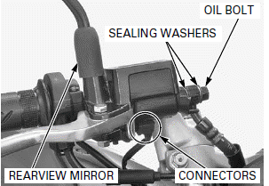
When removing the oil bolt, cover the end of the brake hose to prevent contamination.
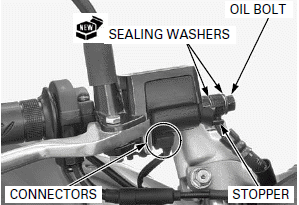
Remove the brake hose oil bolt, sealing washers and brake hose eyelet.
Disconnect the brake light switch connectors.
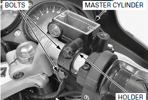
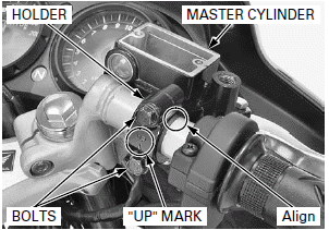
Remove the bolts, holder and master cylinder.
DISASSEMBLY
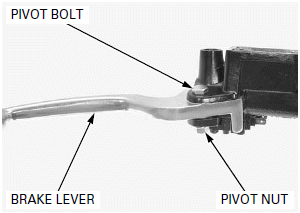
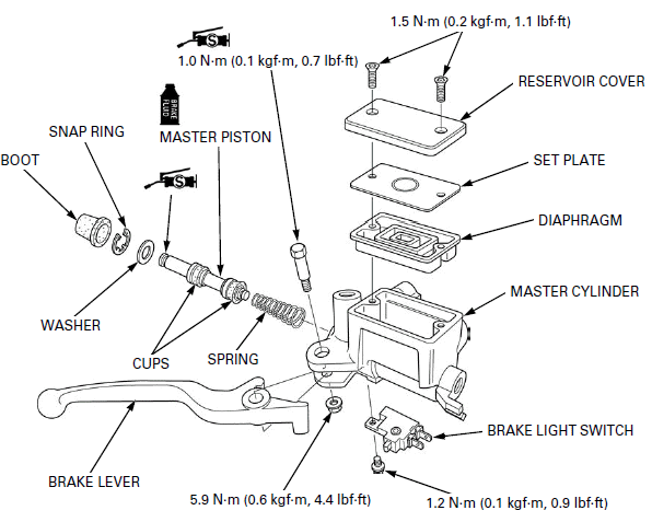
Remove the brake lever pivot nut, bolt and brake lever.
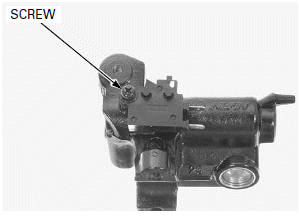
Remove the screw and brake light switch.
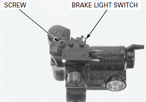
Be careful not to damage the boot.
Remove the boot.
Remove the snap ring using a special tool.
TOOL: Snap ring pliers 07914-SA50001
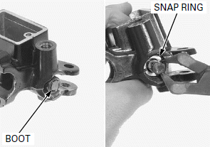
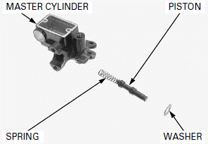
Remove the washer, master piston/spring and separate them.
Clean the inside of the master cylinder, reservoir and master piston with brake fluid.
INSPECTION
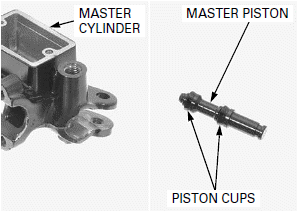
Check the master cylinder for scoring, scratches or damage.
Check the master piston for scoring, scratches or damage.
Check the piston cups for wear, deterioration or damage.
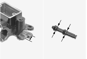
Measure the master cylinder I.D.
SERVICE LIMIT: 11.055 mm (0.4352 in)
Measure the master piston O.D.
SERVICE LIMIT: 10.945 mm (0.4309 in)
ASSEMBLY
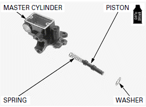
NOTE:
Replace the piston, cups and washer as a set.
Apply brake fluid to the master piston sliding area.
Install the spring onto the piston end.
Do not allow the piston cup lips to turn inside out.
Install the master piston/spring into the master cylinder.
Install the washer.
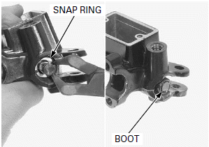
Make sure the snap ring is firmly seated in the groove.
Install the snap ring into the groove of the master cylinder using a special tool.
TOOL: Snap ring pliers 07914-SA50001
Install the boot securely.
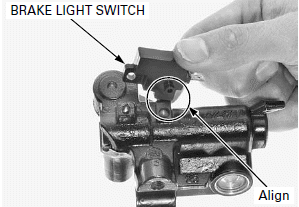
Install the brake light switch to the master cylinder while aligning the brake light switch boss and master cylinder hole.
Install and tighten the brake light switch screw to the specified torque.
TORQUE: 1.2 N-m (0.1 kgf-m, 0.9 lbf-ft)
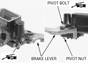
Apply silicone grease to the brake lever contacting area of the master piston and brake lever pivot bolt sliding surface.
Install the brake lever to the master cylinder.
Install and tighten the brake lever pivot bolt to the specified torque.
TORQUE: 1.0 N-m (0.1 kgf-m, 0.7 lbf-ft)
Install and tighten the brake lever pivot nut to the specified torque while holding the brake lever pivot bolt.
TORQUE: 5.9 N-m (0.6 kgf-m, 4.4 lbf-ft)
INSTALLATION
Install the master cylinder, holder ("UP" mark facing up) and bolts.
Align the end of the master cylinder with the punch mark on the handlebar, and tighten the upper bolt first, then the lower bolt.
Connect the brake light switch connectors.
Install the brake hose eyelet with the brake hose oil bolt and new sealing washers.
Push the brake hose eyelet joint against the stopper, then tighten the brake hose oil bolt to the specified torque.
TORQUE: 34 N-m (3.5 kgf-m, 25 lbf-ft)
Install the right rearview mirror.
Fill the reservoir to the upper level and bleed the front brake system.
REAR MASTER CYLINDER
REMOVAL
Drain the brake fluid from the hydraulic system.
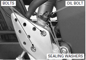
When removing the oil bolt, cover the end of the brake hose to prevent contamination.
Remove the brake hose oil bolt, sealing washers and brake hose eyelet.
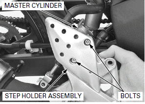
Loosen the master cylinder mounting bolts.
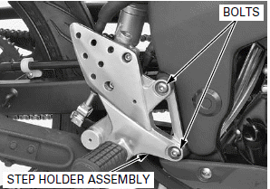
Remove the step holder mounting bolts and right step holder assembly.
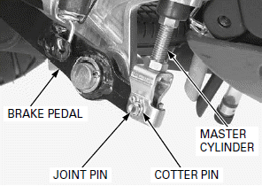
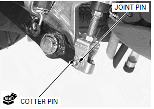
Remove the cotter pin, joint pin and master cylinder from the brake pedal.
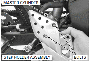
Remove the master cylinder mounting bolts and master cylinder from the right step holder assembly.
DISASSEMBLY
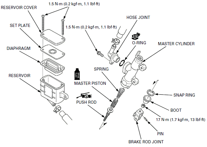
Remove the hose joint screw, O-ring and reservoir hose joint.
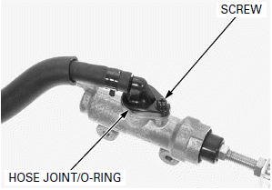
Be careful not to damage the boot.
Remove the boot.
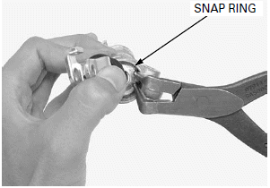
Remove the snap ring using a special tool.
TOOL: Snap ring pliers 07914-SA50001
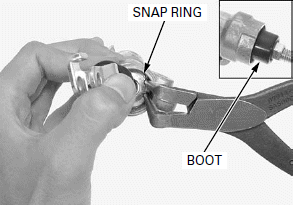
Remove the push rod, master piston/spring and separate them.
Clean the inside of the master cylinder and master piston with brake fluid.
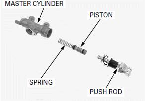
INSPECTION
Check the master cylinder for scoring, scratches or damage.
Check the master piston for scoring, scratches or damage.
Check the piston cups for wear, deterioration or damage.
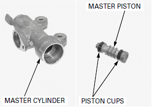
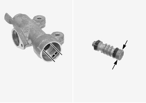
Measure the master cylinder I.D.
SERVICE LIMIT: 12.755 mm (0.5022 in)
Measure the master piston O.D.
SERVICE LIMIT: 12.645 mm (0.4978 in)
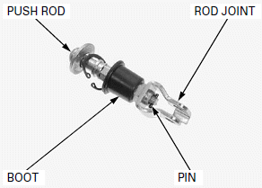
Check the following:
- Push rod for bent
- Boot for damage
- Rod joint for damage
Remove the pin and replace the damaged part if necessary.
ASSEMBLY
NOTE:
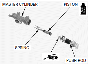
Replace the piston, spring and cups as a set.
Apply brake fluid to the master piston sliding area.
Install the spring onto the piston end.
Do not allow the piston cup lips to turn inside out.
Install the master piston/spring into the master cylinder.
Apply silicone grease to the push rod contacting area.
Install the push rod into the master cylinder.
Make sure the snap ring is firmly seated in the groove.
Install the snap ring into the groove of the master cylinder using a special tool.
TOOL: Snap ring pliers 07914-SA50001
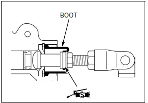
Apply silicone grease to the boot groove of the push rod.
Install the boot securely.
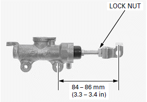
If the push rod joint is reinstalled, adjust the push rod length so that the distance from the center of the master cylinder lower mounting hole to the center of the joint pin hole is 84 - 86 mm (3.3 - 3.4 in) as shown.
After adjustment tighten the push rod lock nut to the specified torque.
TORQUE: 17 N-m (1.7 kgf-m, 12 lbf-ft)
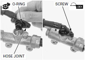
Install a new O-ring to the reservoir hose joint and install them to the master cylinder.
Apply locking agent to the hose joint screw threads and install it Tighten the hose joint screw to the specified torque.
TORQUE: 1.5 N-m (0.2 kgf-m, 1.1 lbf-ft)
INSTALLATION
Install the master cylinder and master cylinder mounting bolts to the right step holder assembly.
Install the master cylinder to the brake pedal and install the joint pin and new cotter pin.
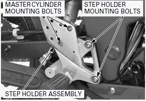
Install the right step holder assembly and step holder mounting bolts.
Tighten the step holder mounting bolts to the specified torque.
TORQUE: 27 N-m (2.8 kgf-m, 20 lbf-ft)
Tighten master cylinder mounting bolts.
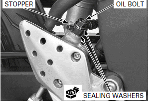
Install the brake hose eyelet with the brake hose oil bolt and new sealing washers.
Push the brake hose eyelet joint against the stopper, then tighten the brake hose oil bolt to the specified torque.
TORQUE: 34 N-m (3.5 kgf-m, 25 lbf-ft)
Fill the reservoir to the upper level and bleed the rear brake system.
See also:
 Honda CBR125RW - Service manual > Brake Fluid Replacement/ Air Bleeding
BRAKE FLUID DRAINING FRONT BRAKE: Turn the handlebar until the reservoir is parallel to the ground. Remove the reservoir cover screws, reservoir cover, set plate and diaphragm.
 Honda CBR125RW - Service manual > Front/Rear Brake Caliper
FRONT BRAKE CALIPER REMOVAL Drain the brake fluid from the hydraulic system. Remove the brake pads. When removing the oil bolt, cover the end of brake hose to prevent contamination.

 BMW G310GS
 Honda CBR125RW
 Husqvarna 401 Vitpilen
 KTM 890 Duke R
 Mash Dirt Track 650
 Peugeot Kisbee
 Yamaha Tracer MT-09
 Honda CBR125RW
 Peugeot Kisbee
 Yamaha Tracer MT-09