 Yamaha Tracer MT09TRA - Service manual > Camshafts


Removing the camshafts
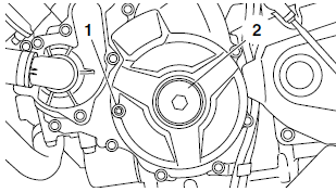
1. Remove:
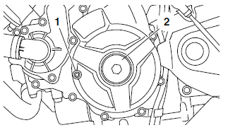
- Timing mark accessing bolt "1"
- Crankshaft end cover "2"
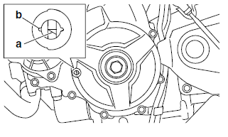
2. Align:
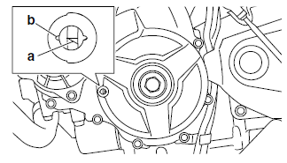
- Mark "a" on the generator rotor (with the generator rotor cover mark "b")
a. Turn the crankshaft counterclockwise.
b. When piston #1 is at BTDC125º on the compression stroke, align the BTDC125º mark "a" on the generator rotor with the generator rotor cover mark "b".
TIP
BTDC125º on the compression stroke can be found when the camshaft lobes are turned away from each other.
3. Remove:
- Timing chain tensioner "1"
- Timing chain tensioner gasket

4. Remove:
- Camshaft cap "1"
- Intake camshaft cap "2"
- Exhaust camshaft cap "3"
NOTICE
To prevent damage to the cylinder head, camshafts or camshaft caps, loosen the camshaft cap bolts in stages and in a crisscross pattern, working from the outside in.

5. Remove:
- Intake camshaft "1"
- Exhaust camshaft "2"
TIP
To prevent the timing chain from falling into the crankcase, fasten it with a wire "3".

6. Remove:
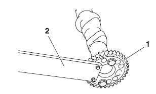
- Camshaft sprocket "1"
TIP
Use the camshaft wrench "2" and loosen the camshaft sprocket bolt.
 Camshaft wrench 90890-04162
Camshaft wrench YM-04162
Checking the camshafts
1. Check:
- Camshaft lobes Blue discoloration/pitting/scratches → Replace the camshaft.
2. Measure:
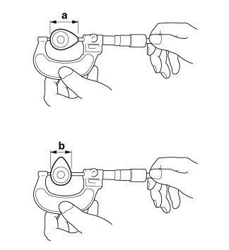
- Camshaft lobe dimensions "a" and "b" Out of specification → Replace the camshaft.
 Camshaft lobe dimensions Lobe height (Intake) 36.290-36.390 mm (1.4287-
1.4327 in)
Limit 36.190 mm (1.4248 in)
Base circle diameter (Intake) 27.950-28.050 mm (1.1004- 1.1043 in)
Limit 27.850 mm (1.0965 in) Lobe height (Exhaust) 35.720-35.820 mm (1.4063- 1.4102 in)
Limit 35.620 mm (1.4024 in)
Base circle diameter (Exhaust) 27.978-28.078 mm (1.1015- 1.1054 in)
Limit 27.878 mm (1.0976 in)
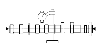
3. Measure:
- Camshaft runout.
Out of specification → Replace.
 Camshaft runout limit 0.030 mm (0.0012 in)
4. Measure:
- Camshaft-journal-to-camshaft-cap clearance Out of specification → Measure the camshaft journal diameter.
 Camshaft-journal-to-camshaftcap
clearance 0.028-0.062 mm (0.0011-0.0024 in)
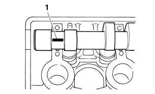
a. Install the camshaft into the cylinder head (without the camshaft caps).
b. Position strip of Plastigauge "1" onto the camshaft journal as shown.
c. Install the dowel pins and camshaft caps.
TIP
- Tighten the camshaft cap bolts in stages and in a crisscross pattern, working from the inner caps out.
- Do not turn the camshaft when measuring the camshaft journal-to-camshaft cap clearance with the Plastigauge.
 Camshaft cap bolt 10 Nm (1.0 m*kgf, 7.2 ft*lbf)
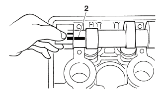
d. Remove the camshaft caps and then measure the width of the Plastigauge "2".
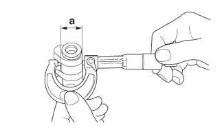
5. Measure:
- Camshaft journal diameter "a".
Out of specification → Replace the camshaft.
Within specification → Replace the cylinder head and the camshaft caps as a set.
 Camshaft journal diameter 24.459-24.472 mm (0.9630- 0.9635 in)
Checking the timing chain and camshaft sprocket
1. Check:
- Timing chain.
Damage/stiffness → Replace the timing chain and camshaft and camshaft sprocket as a set.
2. Check:
- Camshaft sprocket.
More than 1/4 tooth wear "a" → Replace the camshaft sprockets and the timing chain as a set.

a. 1/4 tooth
b. Correct
1. Timing chain
2. Camshaft sprocket
Checking the timing chain guides
The following procedure applies to all of the camshaft sprockets and timing chain guides.
1. Check:
- Timing chain guide (intake side) "1"
- Timing chain guide (top side) "2" Damage/wear → Replace the defective part(s).

Checking the timing chain tensioner
1. Check:
- Timing chain tensioner.
Cracks/damage/rough movement → Replace.
a. Lightly press the timing chain tensioner rod into the timing chain tensioner housing by hand.
TIP
While pressing the timing chain tensioner rod, wind it counterclockwise with a hexagon wrench "1" until it stops.
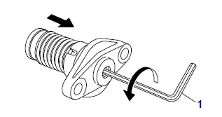
b. Keep pressing the timing chain tensioner rod by hand, remove the hexagon wrench and slowly release the timing chain tensioner rod.
c. Make sure that the timing chain tensioner rod comes out of the timing chain tensioner housing smoothly. If there is rough movement, replace the timing chain tensioner.

Installing the camshafts
1. Remove:
- Timing mark accessing bolt "1"
- Crankshaft end cover "2"

2. Align:
- Mark "a" on the generator rotor (with the generator rotor cover mark "b")
a. Turn the crankshaft counterclockwise.
b. When piston #1 is at BTDC125º, align the mark "a" on the generator rotor with the generator rotor cover mark "b".

3. Install:
- Intake camshaft sprocket "1"
- Exhaust camshaft sprocket "2"
 Camshaft sprocket bolt 24 Nm (2.4 m*kgf, 17 ft*lbf)
NOTICE
Be sure to tighten the camshaft sprocket bolts to the specified torque to avoid the possibility of the bolts coming loose and damaging the engine.
TIP
- Install the camshaft projection "a" at the position shown in the illustration.
- Tighten the camshaft sprocket bolt with the camshaft wrench "3".
 Camshaft wrench 90890-04162
Camshaft wrench YM-04162

4. Install:
- Exhaust camshaft "1"
- Intake camshaft "2"
TIP
- Make sure the punch mark "a" on each camshaft faces up.
- When installing the camshaft, no need to align the mark "b" on the camshaft sprocket.


5. Install:
- Camshaft cap
- Intake camshaft cap
- Exhaust camshaft cap
TIP
- Make sure each camshaft cap is installed in its original place. Refer to the identification marks as follows: "IL": Intake left side camshaft cap mark "EL": Exhaust left side camshaft cap mark
- Make sure the arrow mark "a" on each camshaft points toward the right side of the engine.

6. Tighten:
- Camshaft cap bolts
 Camshaft cap bolt 10 Nm (1.0
m*kgf, 7.2 ft*lbf)
TIP
Tighten the camshaft cap bolts in the tightening sequence as shown.
NOTICE
- Lubricate the camshaft cap bolts with the engine oil.
- The camshaft cap bolts must be tightened evenly or damage to the cylinder head, camshaft caps, and camshafts will result.
- Do not turn the crankshaft when installing the camshaft to avoid damage or improper valve timing.

7. Tighten:
- Camshaft cap bolts "1"
 Camshaft cap bolt 10 Nm (1.0 m*kgf, 7.2 ft*lbf)
TIP
Tighten the camshaft cap bolts in stages and in a crisscross pattern, working from the inner caps out.
NOTICE
- Lubricate the camshaft cap bolts with the engine oil.
- The camshaft cap bolts must be tightened evenly or damage to the cylinder head, camshaft caps, and camshafts will result.
- Do not turn the crankshaft when installing the camshaft to avoid damage or improper valve timing.

8. Check:
Camshaft punch mark "a". Make sure the punch mark "a" on the camshaft is aligned with the camshaft cap alignment mark "b".

9. Install:
- Timing chain tensioner
- Timing chain tensioner gasket

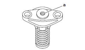
a. Apply a few drops of engine oil to the inside "a" of the timing chain tensioner.
b. While lightly pressing the timing chain tensioner rod by hand, turn the timing chain tensioner rod fully counterclockwise with a hexagon wrench "1".
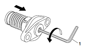
c. Keep pressing the timing chain tensioner rod by hand, remove the hexagon wrench, and then insert the hexagon wrench "2" (Parts No.: 1RC-12228-00) into the timing chain tensioner rod.
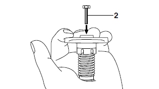
d. Install the timing chain tensioner gasket "3", the timing chain tensioner "4", and the timing chain tensioner bolts "5" on the cylinder block.
TIP
Face the section "b" of the gasket inward.

e. Tighten the timing chain tensioner bolts to the specified torque.
 Timing chain tensioner bolt
10 Nm (1.0 m*kgf, 7.2 ft*lbf) LOCTITE
f. Screw the hexagon wrench by hand until the timing chain tensioner rod touches the timing chain guide, and then tighten 1/4 turn by tool.
TIP
The timing chain tensioner rod is extended by turning the hexagon wrench clockwise.

g. Remove the hexagon wrench, and check the timing chain tension.

h. Install the timing chain tensioner cap bolt and gasket, and then tighten the timing chain tensioner cap bolt to the specified torque.
 Timing chain tensioner cap bolt 7 Nm (0.7 m*kgf, 5.1 ft*lbf)
10.Turn:
- Crankshaft (several turns counterclockwise)
11.Check:
- Mark "a" Make sure the mark "a" on the generator rotor is aligned with the generator rotor cover mark "b".
- Camshaft punch mark "c" Make sure the punch mark "c" on the camshaft is aligned with the camshaft cap alignment mark "d".
Out of alignment → Adjust.
Refer to the installation steps above.

12.Measure:
- Valve clearance Out of specification → Adjust.
Refer to "ADJUSTING THE VALVE CLEARANCE"
13.Install:
- Timing mark accessing bolt "1"
 Timing mark accessing bolt 15 Nm (1.5 m*kgf, 11 ft*lbf)
- Crankshaft end cover "2"
 Crankshaft end cover 10 Nm (1.0 m*kgf, 7.2 ft*lbf)
14.Install:
- Timing chain guide (top side)
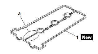
- Cylinder head cover gasket "1"

- Cylinder head cover
 Cylinder head cover bolt 10
Nm (1.0 m*kgf, 7.2 ft*lbf)
TIP
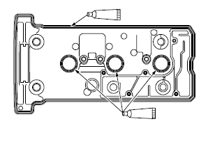
- Apply Three Bond No.1541C onto the mating surfaces of the cylinder head cover and cylinder head cover gasket.
- After installing the cylinder head cover gasket "1" to the cylinder head cover, cut off the "a" section.
15.Install:
- Spark plugs
- Ignition coils "1"
 Spark plug 13 Nm (1.3 m*kgf, 9.4 ft*lbf)
TIP
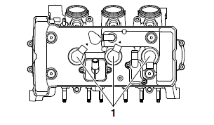
Install the ignition coils "1" in the direction shown in the illustration.
See also:
 Yamaha Tracer MT09TRA - Service manual > Cylinder head
Removing the cylinder head 1. Remove: Intake camshaft Exhaust camshaft

 BMW G310GS
 Honda CBR125RW
 Husqvarna 401 Vitpilen
 KTM 890 Duke R
 Mash Dirt Track 650
 Peugeot Kisbee
 Yamaha Tracer MT-09
 Honda CBR125RW
 Peugeot Kisbee
 Yamaha Tracer MT-09