 Yamaha Tracer MT09TRA - Service manual > Checking the relay unit (diode)
1. Check:
- Relay unit (diode)
Out of specification → Replace.
 Pocket tester 90890-03112
Analog pocket tester YU-03112-C
TIP
The pocket tester or the analog pocket tester readings are shown in the following table.
 Continuity Positive tester
probe sky blue "1"
Negative tester probe black/yellow "2"
No continuity Positive tester probe black/yellow "2"
Negative tester probe sky blue "1"
Continuity Positive tester probe sky blue "1"
Negative tester probe black/red "3"
No continuity Positive tester probe black/red "3"
Negative tester probe sky blue "1"
Continuity Positive tester probe sky blue "1"
Negative tester probe sky blue/white "4"
No continuity Positive tester probe sky blue/white "4"
Negative tester probe sky blue "1"
Continuity Positive tester probe blue/black "5"
Negative tester probe black/red "3"
No continuity Positive tester probe black/red "3"
Negative tester probe blue/black "5"
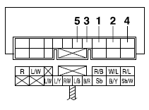
a. Disconnect the relay unit coupler from the wire harness.
b. Connect the pocket tester ( *
1) to the relay unit terminal as shown.
c. Check the relay unit (diode) for continuity.
d. Check the relay unit (diode) for no continuity.
Checking the ignition coils
The following procedure applies to all of the ignition coils.
1. Check:
- Primary coil resistance
Out of specification → Replace.
 Primary coil resistance
1.19-1.61

a. Remove the ignition coil from the spark plug.
b. Connect the pocket tester ( *
1) to the ignition coil as shown.
 Pocket tester 90890-03112
Analog pocket tester YU-03112-C
- Positive tester probe → red/black "1"
- Negative tester probe → Cylinder-#1 ignition coil orange "2" Cylinder-#2 ignition coil gray/red "2" Cylinder-#3 ignition coil orange/green "2"
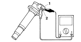
c. Measure the primary coil resistance.
2. Check:
- Secondary coil resistance
Out of specification → Replace.
 Secondary coil resistance
9.35-12.65 k
a. Connect the pocket tester ( *1
k) to the ignition coil as shown.
 Pocket tester 90890-03112
Analog pocket tester YU-03112-C
- Negative tester probe → red/black "1"
- Positive tester probe → spark plug terminal "2"
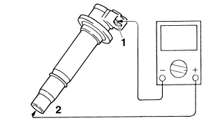
b. Measure the secondary coil resistance.
Checking the ignition spark gap
1. Check:
- Ignition spark gap
Out of specification → Perform the ignition system troubleshooting, starting with step 5.
 Minimum ignition spark gap
6.0 mm (0.24 in)
TIP
If the ignition spark gap is within specification, the ignition system circuit is operating normally.
a. Remove the ignition coil from the spark plug.
b. Connect the ignition checker "1" as shown.
 Ignition checker
90890-06754
Oppama pet-4000 spark checker YM-34487
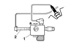
2. Ignition coil
c. Turn the main switch to "ON".
d. Measure the ignition spark gap "a".
e. Crank the engine by pushing the "
 " side of the start/engine stop
switch and gradually increase the spark gap until a misfire occurs.
Checking the crankshaft position sensor
1. Disconnect:
- Crankshaft position sensor coupler (from the wire harness)
2. Check:
- Crankshaft position sensor resistance
Out of specification → Replace the crankshaft position sensor.
 Crankshaft position sensor
resistance 228-342
 (Gy-B)
a. Connect the pocket tester ( *
100) to the crankshaft position sensor coupler as shown.
 Pocket tester 90890-03112
Analog pocket tester YU-03112-C
- Positive tester probe gray "1"
- Negative tester probe black "2"
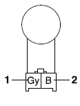
b. Measure the crankshaft position sensor resistance.
See also:
 Yamaha Tracer MT09TRA - Service manual > Checking the relays
Check each switch for continuity with the pocket tester. If the continuity reading is incorrect, replace the relay. Pocket tester 90890-03112
 Yamaha Tracer MT09TRA - Service manual > Checking the lean angle sensor
1. Remove: Lean angle sensor (from the fuel tank bracket) 2. Check: Lean angle sensor output voltage Out of specification → Replace.

 BMW G310GS
 Honda CBR125RW
 Husqvarna 401 Vitpilen
 KTM 890 Duke R
 Mash Dirt Track 650
 Peugeot Kisbee
 Yamaha Tracer MT-09
 Honda CBR125RW
 Peugeot Kisbee
 Yamaha Tracer MT-09