 Yamaha Tracer MT09TRA - Service manual > Checking the lean angle sensor
1. Remove:
- Lean angle sensor (from the fuel tank bracket)
2. Check:
- Lean angle sensor output voltage
Out of specification → Replace.
 Lean angle sensor output
voltage Less than 65º 0.4-1.4 V
More than 65º 3.7-4.4 V
a. Connect the test harness- lean angle sensor (6P) "1" to the lean angle sensor and wire harness as shown.
b. Connect the pocket tester (DC 20 V) to the test harness- lean angle sensor (6P).
 Pocket tester 90890-03112
Analog pocket tester YU-03112-C
Test harness- lean angle sensor (6P) 90890-03209
Test harness- lean angle sensor (6P) YU-03209
- Positive tester probe yellow/green (wire harness color)
- Negative tester probe black/blue (wire harness color)

c. Set the main switch to "ON".
d. Turn the lean angle sensor to 65º.
e. Measure the lean angle sensor output voltage.
Checking the starter motor operation
1. Check:
- Starter motor operation
Does not operate → Perform the electric starting system troubleshooting, starting with step 4.
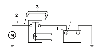
a. Connect the positive battery terminal "1" and starter motor lead "2" with a jumper lead "3".
WARNING
- A wire that is used as a jumper lead must have at least the same capacity of the battery lead, otherwise the jumper lead may burn.
- This check is likely to produce sparks, therefore, make sure no flammable gas or fluid is in the vicinity.

b. Check the starter motor operation.
Checking the stator coil
1. Disconnect:
- Stator coil coupler (from the wire harness)
2. Check:
- Stator coil resistance
Out of specification → Replace the stator coil.
 Stator coil resistance
0.152-0.228
 (W-W)
(W-W)
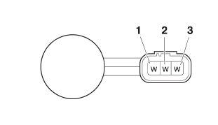
a. Connect the digital circuit tester to the stator coil coupler as shown.
 Digital circuit tester
90890-03174
Model 88 Multimeter with tachometer YU-A1927
- Positive tester probe white "1"
- Negative tester probe white "2"
- Positive tester probe white "1"
- Negative tester probe white "3"
- Positive tester probe white "2"
- Negative tester probe white "3"

b. Measure the stator coil resistance.
Checking the rectifier/regulator
1. Check:
- Rectifier/regulator input voltage
Out of specification → Correct the stator coil condition.
 Rectifier/regulator input voltage above 14 V at 5000 r/min
a. Set the engine tachometer to the ignition coil of cylinder #1.
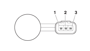
b. Connect the pocket tester (AC 20 V) to the rectifier/regulator coupler as shown.
 Pocket tester 90890-03112
Analog pocket tester YU-03112-C
- Positive tester probe white "1"
- Negative tester probe white "2"
- Positive tester probe white "1"
- Negative tester probe white "3"
- Positive tester probe white "2" - Negative tester probe white "3"

c. Start the engine and let it run at approximately 5000 r/min.
d. Measure the rectifier/regulator input voltage.
2. Check:
- Rectifier/regulator output voltage
Out of specification → Replace the rectifier/ regulator.
 Regulated voltage (DC)
14.3-14.7 V
a. Set the engine tachometer to the ignition coil of cylinder #1.
b. Connect the pocket tester (DC 20 V) to the battery as shown.
 Pocket tester
Analog pocket tester YU-03112-C
- Positive tester probe → positive battery terminal "1"
- Negative tester probe → negative battery terminal "2"

c. Start the engine and let it run at approximately 5000 r/min.
d. Measure the charging voltage.
See also:
 Yamaha Tracer MT09TRA - Service manual > Checking the relay unit (diode)
1. Check: Relay unit (diode) Out of specification → Replace. Pocket tester 90890-03112 Analog pocket tester YU-03112-C
 Yamaha Tracer MT09TRA - Service manual > Checking the horn
1. Check: Horn resistance Out of specification → Replace. Horn Coil resistance 1.07-1.11

 BMW G310GS
 Honda CBR125RW
 Husqvarna 401 Vitpilen
 KTM 890 Duke R
 Mash Dirt Track 650
 Peugeot Kisbee
 Yamaha Tracer MT-09
 Honda CBR125RW
 Peugeot Kisbee
 Yamaha Tracer MT-09