 Honda CBR125RW - Service manual > Clutch/Gearshift Linkage
COMPONENT LOCATION
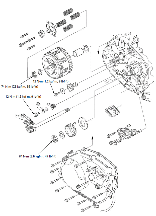
SERVICE INFORMATION
GENERAL
- This section covers service of the clutch and gearshift linkage. All services can be done with the engine installed in the frame.
- Engine oil viscosity and level have an effect on clutch disengagement. Oil additives also effect clutch performance and are not recommended. When the clutch does not disengage or the motorcycle creeps with the clutch lever pulled in, inspect the engine oil level before servicing the clutch system.
- The oil pump removal is required when you remove the washer is located between the primary drive gear and right crankshaft bearing.
SPECIFICATIONS

TORQUE VALUES
Clutch center lock nut 74 N-m (7.5 kgf-m, 55 lbf-ft) Apply engine oil
to the threads and seating surface.
Clutch spring bolt 12 N-m (1.2 kgf-m, 9 lbf-ft)
Primary drive gear lock nut 64 N-m (6.5 kgf-m, 47 lbf-ft) Apply engine
oil to the threads and seating surface.
Shift drum stopper arm bolt 12 N-m (1.2 kgf-m, 9 lbf-ft) Apply locking
agent to the threads.
Shift drum stopper plate bolt 12 N-m (1.2 kgf-m, 9 lbf-ft)
Gearshift return spring pin 25 N-m (2.5 kgf-m, 18 lbf-ft)
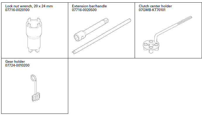
TOOLS
TROUBLESHOOTING
Faulty clutch operation can usually be corrected by adjusting the freeplay.
Clutch lever too hard to pull in
- Damaged, kinked or dirty clutch cable
- Improperly routed clutch cable
- Damaged clutch lifter mechanism
- Faulty clutch lifter plate bearing
Clutch will not disengage or motorcycle creeps with clutch disengaged
- Excessive clutch lever freeplay
- Clutch plate warped
- Engine oil level too high, improper oil viscosity or additive used
- Loosen clutch center lock nut
Clutch slips
- Clutch lifter sticking
- Worn clutch discs
- Weak clutch springs
- No clutch lever freeplay
- Engine oil level too low or oil additive used
Hard to shift
- Misadjusted clutch cable
- Damaged or bent shift fork
- Bent shift fork shaft
- Incorrect engine oil viscosity
- Bent or damaged gearshift spindle
- Damaged shift drum stopper plate
- Damaged shift drum guide grooves
Transmission jumps out of gear
- Worn shift drum stopper arm
- Worn or broken gearshift spindle return spring
- Bent shift fork shaft
- Worn or damaged shift drum stopper plate
- Damaged shift drum guide grooves
- Worn gear dogs or dog holes
Gearshift pedal will not return
- Weak or broken gearshift spindle return spring
- Bent gearshift spindle
RIGHT CRANKCASE COVER
REMOVAL
Drain the engine oil.
Drain the coolant.
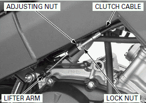
Loosen the lock nut and adjusting nut, then disconnect the clutch cable from the clutch lifter arm.
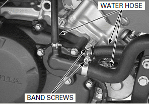
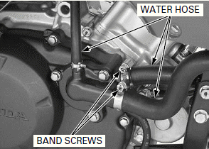
Loosen the water hose band screws and disconnect the water hoses.
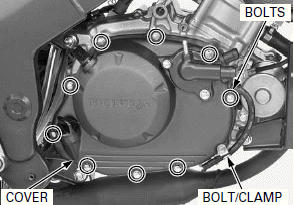
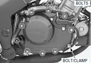
Loosen the right crankcase cover bolts in a crisscross pattern in 2 or 3 steps, and remove the bolts, clamp and right crankcase cover.
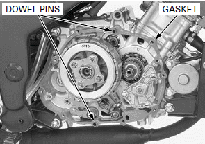
Remove the dowel pins and gasket.
DISASSEMBLY
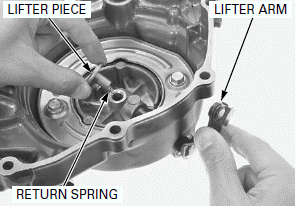
Remove the following:
- Clutch lifter piece
- Clutch lifter arm
- Return spring
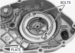
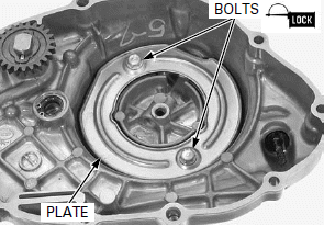
Remove the bolts and plate from the right crankcase cover.
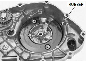
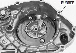
Remove the rubber from the right crankcase cover.
INSPECTION
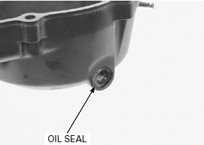
Check the clutch lifter arm oil seal for wear or damage and replace if necessary.
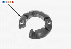
Check the rubber for damage and replace if necessary.
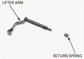
Check the following:
- Lifter arm for wear or damage
- Return spring for fatigue or damage
ASSEMBLY
Install the rubber to the right crankcase cover.
Install the plate to the right crankcase cover.
Apply locking agent to the right crankcase cover plate bolt threads.
Install and tighten the bolts.
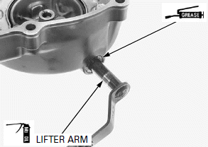
Apply grease to the clutch lifter arm oil seal lips.
Apply molybdenum oil solution to the clutch lifter arm sliding surface and arm end.
Install the clutch lifter arm.
Apply molybdenum oil solution to the clutch lifter arm hole inner surface.
Install the return spring to the right crankcase cover by aligning the spring upper end with the hole of the clutch lifter arm.
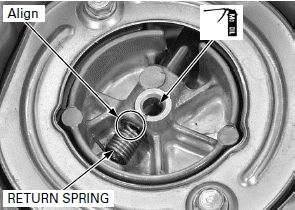
Install the lifter piece to the clutch lifter arm groove while aligning the groove with the lifter piece hole.
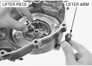
INSTALLATION
Be careful not to damage the mating surfaces.
Clean any gasket material from the mating surfaces of the right crankcase and cover.
Install the dowel pins and a new gasket.
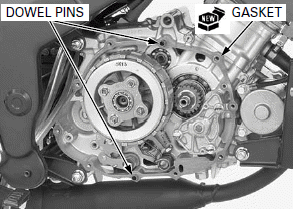
Install the right crankcase cover, clamp and bolts.
Tighten the bolts in a crisscross pattern in 2 or 3 steps.
Connect the water hoses and tighten the water hose band screws.
Connect the clutch cable.
Adjust the clutch lever freeplay.
Fill the engine with the recommended engine oil.
Fill the recommended coolant mixture to the filler neck and bleed the air.
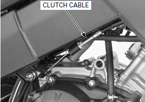
CLUTCH
REMOVAL
Remove the right crankcase cover.
Remove the clutch lifter bearing.
Remove the clutch spring bolts in a crisscross pattern in 2 or 3 steps.
Remove the clutch lifter plate and clutch springs.
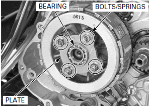
Install the clutch center holder and tighten the clutch spring bolts securely.
Loosen the clutch center lock nut using the special tools.
TOOLS:
Clutch center holder 07GMB-KT70101
Lock nut wrench, 20 x 24 mm 07716-0020100
Extension bar/handle 07716-0020500
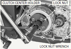
Remove the clutch center lock nut and washer.
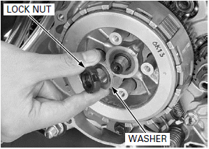
Remove the following:
- Clutch center
- Clutch disc
- Clutch plates
- Pressure plate
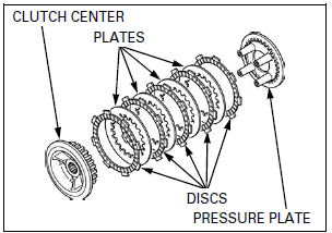
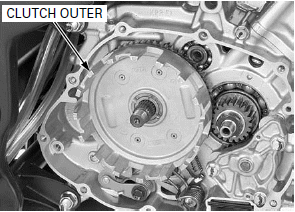
Remove the clutch outer.
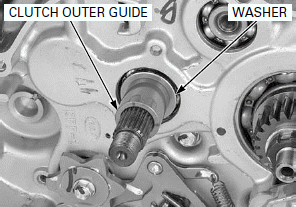
Remove the clutch outer guide and washer from the mainshaft.
INSPECTION
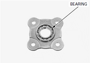
CLUTCH LIFTER BEARING
Turn the inner race of the lifter plate bearing with your finger.
The bearing should turn smoothly and quietly.
Also check that the bearing outer race fits tightly in the lifter plate.
Replace the bearing if the inner race does not turn smoothly, quietly, or if the outer race fits loosely in the lifter plate.
CLUTCH SPRING
Replace the clutch springs as a set.
Check the clutch spring for fatigue or damage.
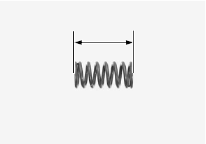
Measure the free length of the clutch spring.
SERVICE LIMIT: 38.3 mm (1.51 in)
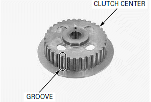
CLUTCH CENTER
Check the grooves of the clutch center for nicks, indentations or abnormal wear made by the clutch plates.
CLUTCH DISC
Replace the clutch discs and plates as a set.
Replace the clutch discs if they show signs of scoring or discoloration.
Measure the disc thickness of each disc.
SERVICE LIMIT: 2.65 mm (0.104 in)

CLUTCH PLATE
Replace the clutch discs and plates as a set.
Check the plate for discoloration.
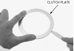
Check the clutch plate for warpage on a surface plate using a feeler gauge.
SERVICE LIMIT: 0.20 mm (0.008 in)
Warped clutch plates prevent the clutch from disengaging properly.
CLUTCH OUTER/OUTER GUIDE
Check the slots of the clutch outer for nicks, cuts or indentations made by the clutch discs.
Check the primary driven gear teeth for wear or damage.
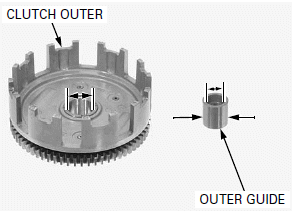
Measure the clutch outer I.D.
SERVICE LIMIT: 30.54 mm (1.202 in)
Measure the clutch outer guide I.D. and O.D.
SERVICE LIMITS:
I.D.: 17.04 mm (0.671 in)
O.D.: 22.93 mm (0.903 in)
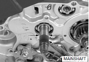
MAINSHAFT
Measure the mainshaft O.D. at the clutch outer guide.
SERVICE LIMIT: 16.59 mm (0.653 in)
INSTALLATION
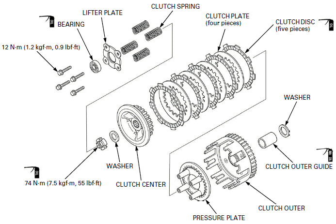
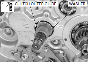
Install the washer to the mainshaft.
Apply molybdenum oil solution to the clutch outer guide outer surface and install it to the mainshaft.
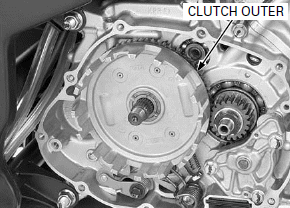
Install the clutch outer.
Apply engine oil to the clutch disc entire surfaces.
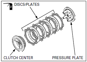
Assemble clutch discs, clutch plates and pressure plate onto clutch center,
while aligning " " mark of clutch
center and pressure plate.
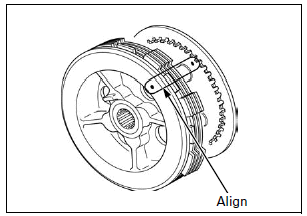
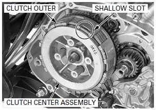
Install the tabs of the clutch disc (out side) into the shallow slots in the clutch outer.
Install the clutch center assembly into the clutch outer.
Install the washer.
Apply engine oil to the clutch center lock nut threads and seating surface and install it.
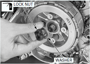
Attach the clutch center holder to the pressure plate using the clutch spring bolts to hold the clutch center, then tighten the clutch center lock nut to the specified torque using the special tools.
TOOLS:
Clutch center holder 07GMB-KT70101
Lock nut wrench, 20 x 24 mm 07716-0020100
Extension bar/handle 07716-0020500
TORQUE: 74 N-m (7.5 kgf-m, 55 lbf-ft)
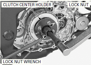
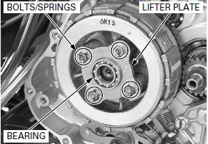
Install the clutch springs, lifter plate and bolts.
Tighten the lifter plate bolts to the specified torque in a crisscross pattern in 2 or 3 steps.
TORQUE: 12 N-m (1.2 kgf-m, 9 lbf-ft)
Install the clutch lifter bearing.
Install the right crankcase cover.
GEARSHIFT LINKAGE
REMOVAL
Remove the following:
- Right crankcase cover
- Clutch assembly
- Gearshift arm
Clean the gearshift spindle end.
Remove the shift drum stopper arm bolt and shift drum stopper arm while holding the shift drum stopper arm using a screwdriver.
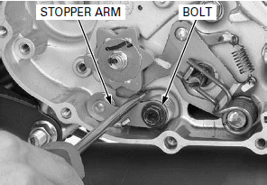
Pull down the spindle arm, then pull out the gearshift spindle assembly from the crankcase.
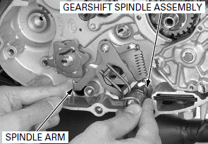
Remove the following:
- Shift drum stopper plate bolt
- Washer
- Shift drum stopper plate
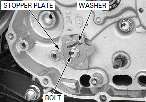
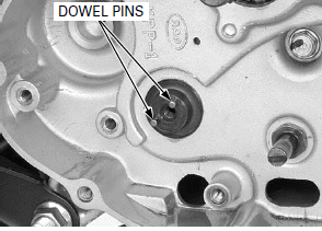
Remove the dowel pins from the shift drum.
INSPECTION
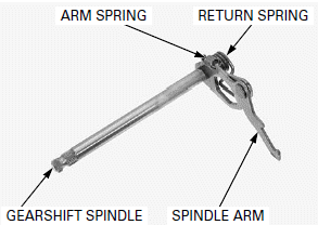
Check the return spring and spindle arm spring for fatigue or damage replace them if necessary.
Check the gearshift spindle for wear or bend.
Check the spindle arm for wear, damage or deformation.
Replace the gearshift spindle as an assembly if necessary.
INSTALLATION
Install the dowel pin into the shift drum hole.
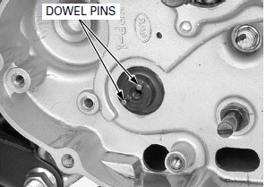
Install the shift drum stopper plate, while aligning the pins hole with the dowel pins.
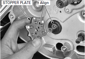
Install the shift drum stopper plate bolt and washer to the shift drum stopper plate and install them.
Tighten the bolt to the specified torque.
TORQUE: 12 N-m (1.2 kgf-m, 9 lbf-ft)
Remove the gearshift spindle oil seal.
Apply grease to a new gearshift spindle oil seal lips.
Install the gearshift spindle oil seal until it is flush with the crankcase surface.
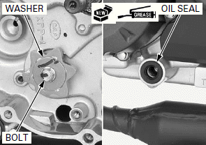
Apply molybdenum oil solution to the gearshift spindle shaft outer surface.
Install the gearshift spindle assembly to the crankcase by aligning the return spring ends with the spring pin while pushing down the spindle arm and set the spindle arm to the shift drum pins.
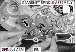
Apply 6.5 +- 1.0 mm (0.26 +- 0.04 in) from tip of locking agent to the shift drum stopper arm bolt threads.
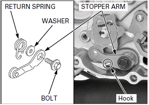
Install the return spring, washer, stopper arm with hooking the return spring at the stopper arm groove.
Install and tighten the bolt to the specified torque.
TORQUE: 12 N-m (1.2 kgf-m, 9 lbf-ft)
Check the stopper arm for proper operation.
Install the following:
- Gearshift arm
- Clutch assembly
- Right crankcase cover
GEARSHIFT PEDAL
REMOVAL
Remove the lower cowl
When removing the gearshift pedal, mark the pedal position to ensure correct reassembly in its original location.
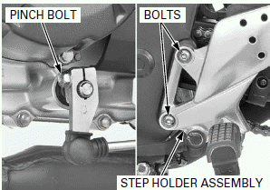
Remove the pinch bolt and gearshift arm.
Remove the left step holder mounting bolts and left step holder assembly.
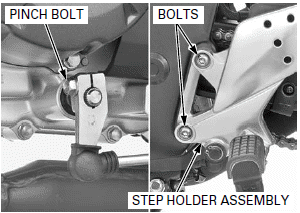
DISASSEMBLY/ASSEMBLY
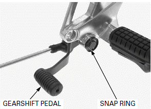
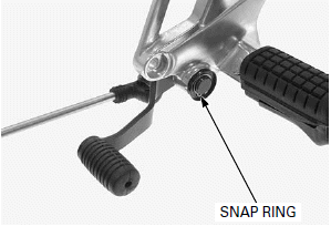
Remove the snap ring and gearshift pedal.
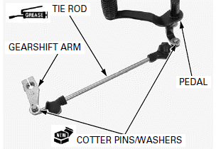
Remove the cotter pins and washers then remove the gearshift tie rod from the gearshift pedal and gearshift arm.
Apply grease to the gearshift tie rod sliding area and install the gearshift pedal and gearshift arm.
Install the washers and new cotter pins.
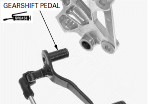
Apply grease to the gearshift pedal pivot sliding area.
Install the gearshift pedal to the left step holder.
Make sure the snap ring is firmly seated in the groove.
Install the snap ring.
INSTALLATION
Install the left step holder assembly and left step holder mounting bolts, tighten the bolts to the specified torque.
TORQUE: 27 N-m (2.8 kgf-m, 20 lbf-ft)
Install the gearshift arm on its original position as marked during removal.
Install and tighten the pinch bolt securely.
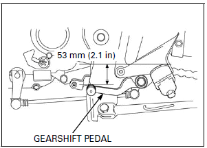
Standard pedal height is 53 mm (2.1 in) below the top of the left step as shown.
PRIMARY DRIVE GEAR
REMOVAL
NOTE:
If you replace the primary drive gear, be careful to select the identification color of the primary drive gear.
Remove the following:
- Clutch assembly
- Oil pump
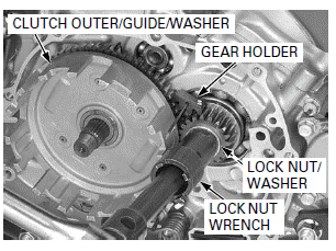
Temporarily install the washer, clutch outer guide and clutch outer.
Insert the gear holder between the primary drive and driven gears.
Loosen the primary drive gear lock nut using the special tools.
TOOLS:
Lock nut wrench, 20 x 24 mm 07716-0020100
Gear holder 07724-0010200
Extension bar/handle 07716-0020500
Remove the clutch outer, clutch outer guide, lock nut and washers.
Remove the primary drive gear.
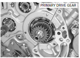
Be careful not to damage the key groove and crankshaft.
Remove the woodruff key and washer.
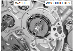
INSTALLATION
Install the washer.
Be careful not to damage the key groove and crankshaft.
Install the woodruff key onto the crankshaft.
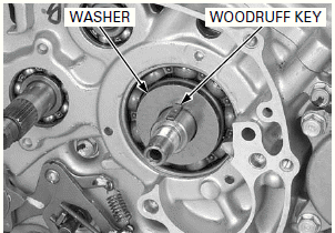
Install the primary drive gear, while aligning the groove with the woodruff key.
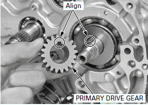
Install the washer.
Apply engine oil to the primary drive gear lock nut threads and seating surface, and install it.
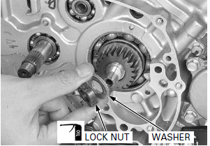
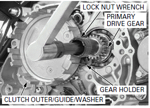
Temporarily install the washer, clutch outer guide and clutch outer.
Insert the gear holder between the primary drive and driven gears.
Tighten the primary drive gear lock nut to the specified torque using the special tools.
TORQUE: 64 N-m (6.5 kgf-m, 47 lbf-ft)
TOOLS:
Lock nut wrench, 20 x 24 mm 07716-0020100
Gear holder 07724-0010200
Extension bar/handle 07716-0020500
Install the following:
- Oil pump
- Clutch assembly
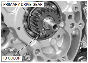
PRIMARY DRIVE GEAR SELECTION
The primary drive gear has identification color.
PRIMARY DRIVE GER SELECTION TABLE

If the primary drive gear is replaced with a new one, select the same colored gear as the original gear.
If the crankcase is replaced with a new one, select the blue marked gear.
See also:
 Honda CBR125RW - Service manual > Cylinder/Piston
COMPONENT LOCATION SERVICE INFORMATION
 Honda CBR125RW - Service manual > Alternator/Starter Clutch
COMPONENT LOCATION SERVICE INFORMATION

 BMW G310GS
 Honda CBR125RW
 Husqvarna 401 Vitpilen
 KTM 890 Duke R
 Mash Dirt Track 650
 Peugeot Kisbee
 Yamaha Tracer MT-09
 Honda CBR125RW
 Peugeot Kisbee
 Yamaha Tracer MT-09