 Honda CBR125RW - Service manual > Alternator/Starter Clutch
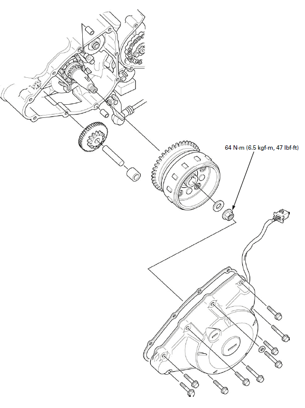
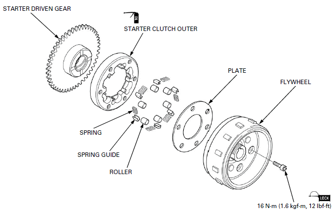
COMPONENT LOCATION
SERVICE INFORMATION
GENERAL
- This section covers the removal and installation of the flywheel, alternator and starter clutch. These services can be done with the engine installed in the frame.
SPECIFICATIONS

TORQUE VALUES
Flywheel nut 64 N-m (6.5 kgf-m, 47 lbf-ft) Apply engine oil to the
threads and seating surface.
CKP sensor bolt 10 N-m (1.0 kgf-m, 7 lbf-ft) Apply locking agent to the
threads.
Stator mounting bolt 10 N-m (1.0 kgf-m, 7 lbf-ft)
Starter clutch bolt 16 N-m (1.6 kgf-m, 12 lbf-ft) Apply locking agent to
the threads.
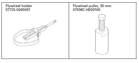
TOOLS
TROUBLESHOOTING
Engine does not turn
- Faulty starter clutch
- Damaged reduction gear/shaft
- Faulty starter driven gear
LEFT CRANKCASE COVER
REMOVAL
Remove the lower cowl.
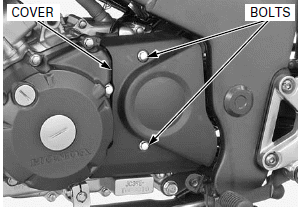
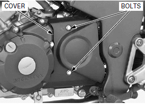
Remove the bolts and drive sprocket cover.
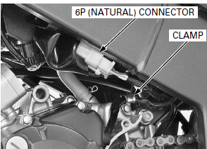
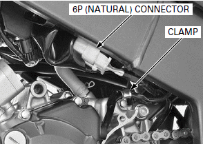
Disconnect the alternator/CKP sensor 6P (Natural) connector.
Release the alternator/CKP sensor wire from the clamp.
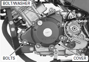
The left crankcase cover (stater) is magnetically attracted to the flywheel, be careful during removal.
Loosen the left crankcase cover bolts in a crisscross pattern in 2 or 3 steps and remove the bolts, washer and left crankcase cover.
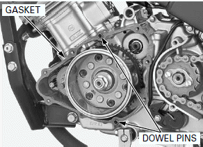
Remove the dowel pins and gasket.
INSTALLATION
Be careful not to damage the mating surfaces.
Clean any gasket material from the mating surfaces of the right crankcase and cover.
Install the dowel pins and new gasket.
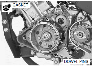
The left crankcase cover (stater) is magnetically attracted to the flywheel, be careful during installation.
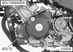
Install the left crankcase cover, bolts and washer.
Tighten the bolts in a crisscross pattern in 2 or 3 steps.
Connect the alternator/CKP sensor 6P (Natural) connector.
Route the wire properly.
Install the alternator/CKP sensor wire to the clamp.
Install the bolts and drive sprocket cover.
Install the lower cowl.
STATOR/CKP SENSOR
REMOVAL
Remove the left crankcase cover.
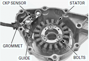
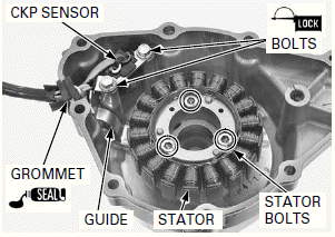
Remove the grommet.
Remove the CKP sensor bolts, wire guide, CKP sensor, stator mounting bolts and stator from the left crankcase cover.
INSTALLATION
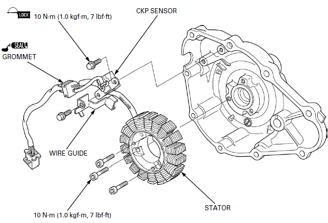
Install the stator.
Install and tighten the stator mounting bolts to the specified torque.
TORQUE: 10 N-m (1.0 kgf-m, 7 lbf-ft)
Apply liquid sealant (TB 1215 or equivalent) to the wire grommet sealing surface and install the grommet into the groove.
Install the wire guide and CKP sensor.
Apply 6.5 +- 1.0 mm (0.26 +- 0.04 in) from tip of locking agent to the CKP sensor bolt threads.
Install and tighten the bolts to the specified torque.
TORQUE: 10 N-m (1.0 kgf-m, 7 lbf-ft)
FLYWHEEL REMOVAL
Remove the left crankcase cover.
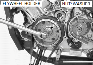
Hold the flywheel with a special tool and remove the flywheel nut and washer.
TOOL: Flywheel holder 07725-0040001
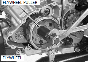
Remove the flywheel using a special tool.
TOOL: Flywheel puller, 30mm 07KMC-HE00100
Remove the collar, starter reduction gear and shaft.
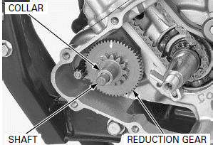
Check the starter reduction gear and shaft for wear or damage.
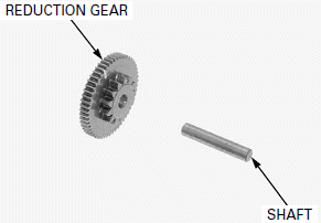
Be careful not to damage the key groove and crankshaft.
Remove the woodruff key.
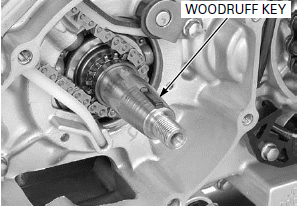
STARTER CLUTCH
REMOVAL
Remove the flywheel.
Remove the starter driven gear while turning it counterclockwise.
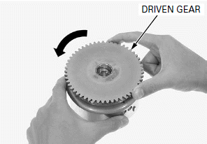
Hold the flywheel with a special tool and remove the starter clutch torx screws.
TOOL: Flywheel holder 07725-0040001
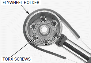
Remove the starter clutch assembly from the flywheel.
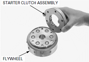
DISASSEMBLY
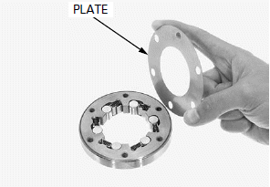
Remove the plate.
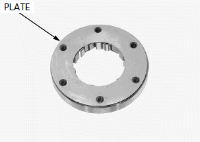
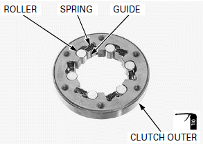
Remove the rollers, spring guides and springs from the starter clutch outer.
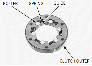
INSPECTION
Check the rollers, spring guides, springs and starter clutch outer for wear or damage.
Replace the rollers as a set.
Replace the rollers for wear or damage.
NOTE:
Starter clutch should replaced as an assembly if the starter clutch and springs are damaged or worn.
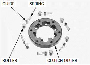
Check the starter driven gear teeth for wear or damage.
Check the roller contact surface for wear or damage.
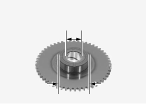
Measure the starter driven gear boss I.D.
SERVICE LIMIT: 22.08 mm (0.869 in)
Measure the starter driven gear boss O.D.
SERVICE LIMIT: 45.60 mm (1.795 in)
ASSEMBLY
Install the springs, spring guides and rollers into the starter clutch outer.
Apply engine oil to the starter clutch rolling surface.
Install the plate.
INSTALLATION
Install the starter clutch assembly to the flywheel as shown.
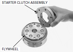
Apply 6.5 +- 0.1 mm (0.26 +- 0.04 in) from tip of locking agent to the starter clutch torx screw threads.
Install the starter clutch assembly onto the flywheel and install the torx screws.
Hold the flywheel with a special tool and tighten the torx screws to the specified torque.
TOOL: Flywheel holder 07725-0040001
TORQUE: 16 N-m (1.6 kgf-m, 12 lbf-ft)
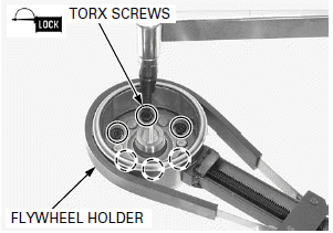
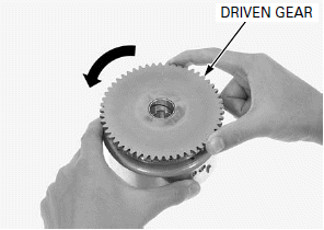
Install the starter driven gear while turning it counterclockwise.
Make sure that the starter driven gear turns counterclockwise smoothly and does not turn clockwise.
Install the flywheel.
FLYWHEEL INSTALLATION
Clean any oil from the crankshaft taper.
Be careful not to damage the key groove and crankshaft.
Install the woodruff key onto the crankshaft.
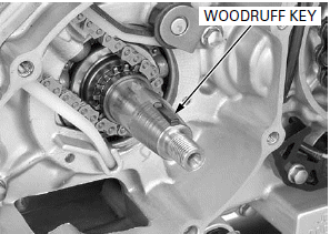
Apply engine oil to the starter reduction gear shaft outer surface.
Install the shaft, starter reduction gear and collar.
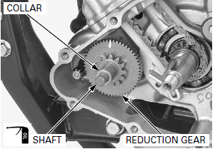
Apply engine oil to the left crankshaft starter driven gear sliding surface.
Install the flywheel while aligning the woodruff key on the crankshaft with flywheel keyway.
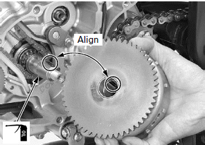
Apply engine oil to the flywheel nut threads and seating surface.
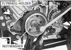
Install the washer and nut.
Hold the flywheel with a special tool and tighten the nut to the specified torque.
TOOL: Flywheel holder 07725-0040001
TORQUE: 64 N-m (6.5 kgf-m, 47 lbf-ft)
Install the left crankcase cover.
See also:
 Honda CBR125RW - Service manual > Clutch/Gearshift Linkage
COMPONENT LOCATION SERVICE INFORMATION
 Honda CBR125RW - Service manual > Crankshaft/Balancer/Transmission
COMPONENT LOCATION SERVICE INFORMATION

 BMW G310GS
 Honda CBR125RW
 Husqvarna 401 Vitpilen
 KTM 890 Duke R
 Mash Dirt Track 650
 Peugeot Kisbee
 Yamaha Tracer MT-09
 Honda CBR125RW
 Peugeot Kisbee
 Yamaha Tracer MT-09