 Honda CBR125RW - Service manual > Cooling System
SYSTEM FLOW PATTERN
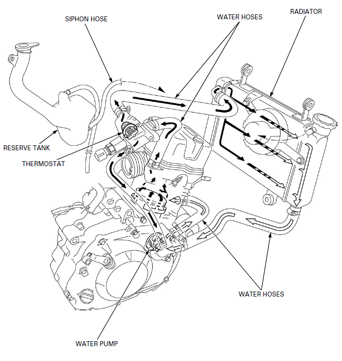
- RESERVE TANK
- SIPHON HOSE
- THERMOSTAT
- WATER HOSES
- RADIATOR
- WATER PUMP
SERVICE INFORMATION
GENERAL
! WARNING
Removing the radiator cap while the engine is hot can allow the coolant to spray out, seriously scalding you.
Always let the engine and radiator cool down before removing the radiator cap.

Using coolant with silicate inhibitors may cause premature wear of water pump seals or blockage of radiator passages.
Using tap water may cause engine damage.
- Add cooling system at the reserve tank. Do not remove the radiator cap except to refill or drain the system.
- All cooling system services can be done with the engine installed in the frame.
- Avoid spilling coolant on painted surfaces.
- After servicing the system, check for leaks with a cooling system tester.
SPECIFICATIONS

TORQUE VALUES
Water pump impeller 10 N-m (1.0 kgf-m, 7 lbf-ft)
Thermostat housing cover bolt 13 N-m (1.3 kgf-m, 10 lbf-ft)
Cooling fan nut 1.0 N-m (0.1 kgf-m, 0.7 lbf-ft) Apply locking agent to
the threads.
Fan motor screw 2.8 N-m (0.3 kgf-m, 2.1 lbf-ft)
Fan motor shroud mounting bolt 8.4 N-m (0.9 kgf-m, 6.2 lbf-ft)
Water hose band screw -
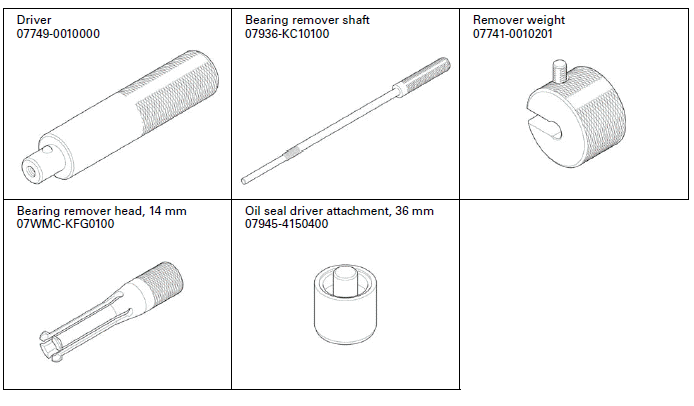
TOOLS
TROUBLESHOOTING
Engine temperature too high
- Faulty temperature gauge or ECT sensor
- Thermostat stuck closed
- Faulty radiator cap
- Insufficient coolant
- Passage blocked in radiator, hoses or water jacket
- Air in system
- Faulty cooling fan motor
- Faulty fan control relay
- Faulty water pump
Engine temperature too low
- Faulty temperature gauge or ECT sensor
- Thermostat stuck open
- Faulty fan control relay
Coolant leak
- Faulty water pump mechanical seal
- Deteriorated O-ring
- Faulty radiator cap
- Damaged or deteriorated cylinder head gasket
- Loose hose connection or clamp
- Damaged or deteriorated hoses
- Damaged radiator
SYSTEM TESTING
COOLANT (HYDROMETER TEST)
Remove the inner cowl.
Remove the screw and radiator cap.
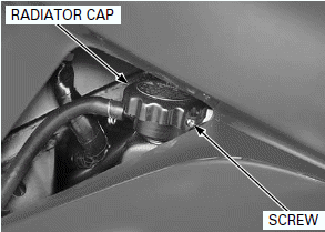
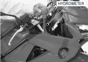
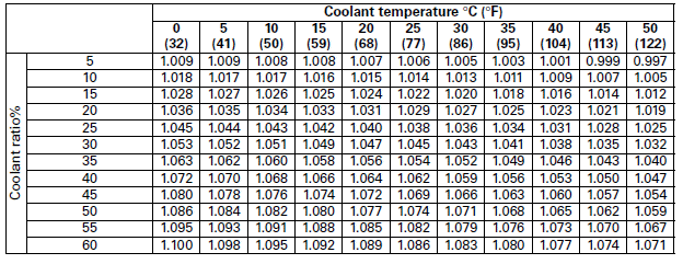
Test the coolant gravity using a hydrometer (see below for "COOLANT GRAVITY CHART").
Look for contamination and replace the coolant if necessary.
After checking the gravity, install the radiator cap and screw securely.
Install the inner cowl.
COOLANT GRAVITY CHART
RADIATOR CAP/SYSTEM PRESSURE INSPECTION
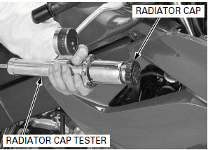
Remove the radiator cap.
Wet the sealing surfaces of the cap, then install the cap onto the tester.
Pressurize the radiator cap using the tester. Replace the radiator cap if it does not hold pressure, or if relief pressure is too high or too low. It must hold the specified pressure for at least 6 seconds.
RADIATOR CAP RELIEF PRESSURE: 93.2 - 122.6 kPa (0.95 - 1.25 kgf/cm2, 13.5 - 17.8 psi)
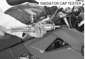
Pressurize the radiator, engine and hoses using the tester, and check for leaks.

Excessive pressure can damage the cooling system components. Do not exceed 122.6 kPa (1.25 kgf/cm2, 17.8 psi).
Repair or replace components if the system will not hold the specified pressure for at least 6 seconds.
Remove the tester.
Install the radiator cap.
COOLANT REPLACEMENT
PREPARATION
NOTE:
- The effectiveness of coolant decreases with the accumulation of rust or if there is a change in the mixing proportion during usage. Therefore, for best performance change the coolant regularly as specified in the maintenance schedule.
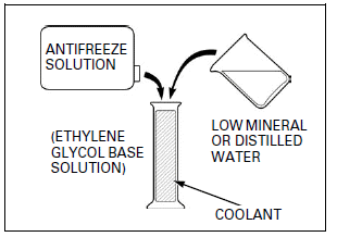
- Mix only distilled, low mineral water with the recommended antifreeze.
RECOMMENDED ANTIFREEZE (Except CM type): High quality ethylene glycol antifreeze containing silicate-free corrosion inhibitors
RECOMMENDED ANTIFREEZE (CM type only): Pro Honda HP coolant or equivalent high quality ethylene glycol antifreeze containing silicate-free corrosion inhibitors
STANDARD COOLANT CONCENTRATION: 1:1 (mixture with distilled water)
REPLACEMENT/AIR BLEEDING
Remove the following:
- Lower cowl
- Radiator cap
- Single seat
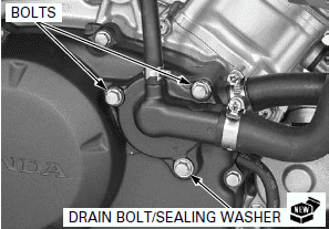
Remove the drain bolt on the water pump cover and drain the system coolant.
Reinstall the drain bolt with a new sealing washer.
Install and tighten the drain bolt securely.
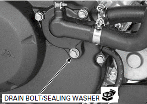
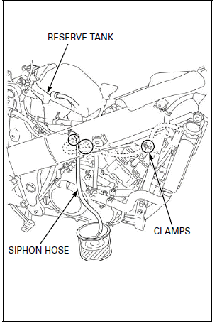
Disconnect the siphon hose from the radiator and release it to the clamps.
Drain the coolant from the reserve tank.
Empty the coolant and rinse the inside of the reserve tank with water.
Install the siphon hose to the clamps and connect it to the radiator.
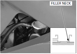
When filling the system or reserve tank with a coolant (checking coolant level), support the motorcycle on a level surface.
Fill the system with the recommended coolant through the filler opening up to filler neck.
Bleed air from the system as follows:
1. Shift the transmission into neutral.
Start the engine and let it idle for 2 - 3 minutes.
2. Snap the throttle 3 - 4 times to bleed air from the system.
3. Stop the engine and add the coolant up to the filler neck.
4. Install the radiator cap
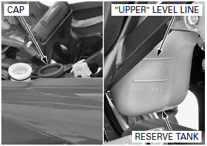
Remove the reserve tank cap and fill the reserve tank to the "UPPER" level line.
Install the reserve tank cap.
Install the following:
- Single seat
- Lower cowl
THERMOSTAT
REMOVAL
Drain the coolant.
Lift and support the fuel tank.
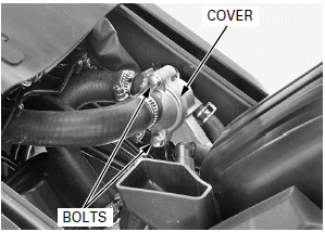
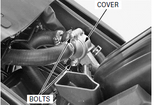
Remove the bolts and thermostat housing cover.
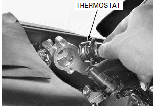
Remove the thermostat from the thermostat housing.
INSPECTION
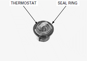
Visually inspect the thermostat for damage.
Check for damage of the seal ring.
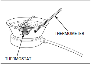
Wear insulated gloves and adequate eye protection. Keep flammable materials away from the electric heating element.
Do not let the thermostat or thermometer touch the pan, or you will get false reading.
Heat the water with an electric heating element to operating temperature for 5 minutes.
Suspend the thermostat in heated water to check its operation.
THERMOSTAT BEGIN TO OPEN: 74 - 78ºC (165 - 172ºF)
VALVE LIFT: 3.5 - 4.5 mm (0.14 - 0.18 in) minimum at 85ºC (185ºF)
Replace the thermostat if the valve open at a temperatures other than those specified.
INSTALLATION
Install the thermostat into the housing.
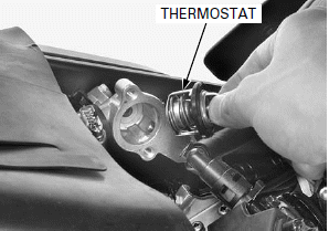
Install the thermostat housing cover onto the housing.
Install and tighten the housing cover bolts to the specified torque.
TORQUE: 13 N-m (1.3 kgf-m, 10 lbf-ft)
Remove the suitable support and close the fuel tank.
Fill the system with the recommended coolant and bleed any air.
THERMOSTAT HOUSING
REMOVAL/INSTALLATION
Drain the coolant.
Lift and support the fuel tank.
Disconnect the ECT sensor 3P (Gray) connector.
Loosen the water hose band screws and disconnect the water hose from the thermostat housing.
Remove the bolt and thermostat housing.
Install the thermostat housing in the reverse order of removal.
Fill the recommended coolant mixture to the filler neck and bleed the air.

RADIATOR
REMOVAL
Drain the coolant.
Lift and support the fuel tank.
Remove the middle cowl.
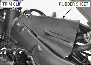
Remove the trim clip.
Open the rubber sheet.
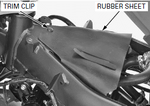
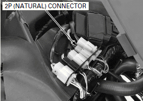
Disconnect the fan motor 2P (Natural) connector.
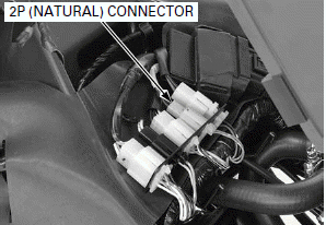
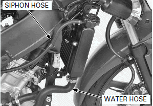
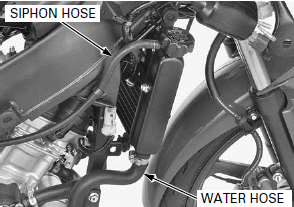
Disconnect the siphon hose from the radiator.
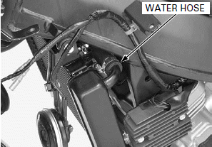
Loosen the water hose band screw and disconnect the lower water hose.
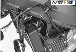
Loosen the water hose band screw and disconnect the upper water hose.
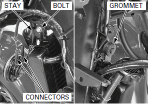
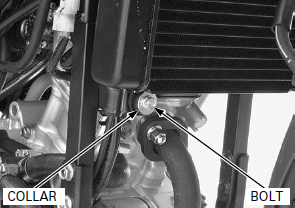
Remove the radiator lower mounting bolt and collar.

Disconnect the horn connectors.
Remove the radiator upper mounting bolt and horn mounting stay.
Be careful not to damage the radiator fins.
Release the radiator upper grommet from the frame boss by moving the radiator to the right, then remove the radiator assembly.
DISASSEMBLY
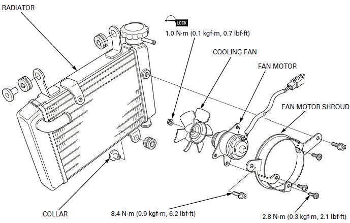
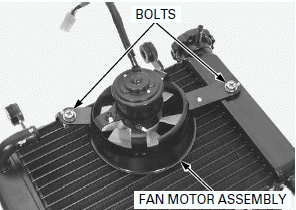
Remove the bolts and fan motor assembly from the radiator.
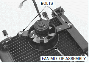
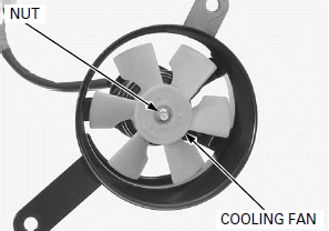
Remove the cooling fan nut and cooling fan.
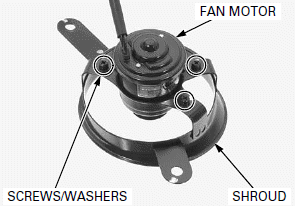
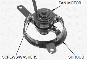
Remove the screws and fan motor from the fan motor shroud.
ASSEMBLY
Install the fan motor onto the fan motor shroud.
Install and tighten the screws to the specified torque.
TORQUE: 2.8 N-m (0.3 kgf-m, 2.1 lbf-ft)
Install the cooling fan onto the fan motor shaft by aligning the flat surfaces.
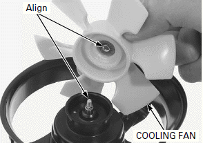
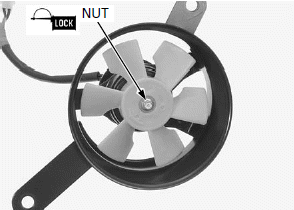
Apply locking agent to the cooling fan nut threads.
Install and tighten the nut to the specified torque.
TORQUE: 1.0 N-m (0.1 kgf-m, 0.7 lbf-ft)
Install the fan motor assembly onto the radiator.
Install and tighten the bolts to the specified torque.
TORQUE: 8.4 N-m (0.9 kgf-m, 6.2 lbf-ft)
INSTALLATION
Be careful not to damage the radiator fins.
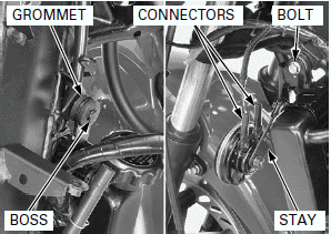
Install the radiator assembly, aligning its upper grommet with the frame boss.
Install the horn mounting stay and radiator upper mounting bolt and tighten the bolt.
Connect the horn connectors.
Install the collar and radiator lower mounting bolt.
Connect the upper water hose and tighten the water hose band screw.
Connect the lower water hose and siphon hose.
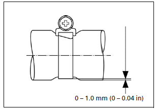
Tighten the water hose band screws as shown.
After installation, check the radiator and radiator hoses for leaks.
Connect the fan motor 2P (Natural) connector.
Close the rubber sheet.
Install the trim clip.
Install the middle cowl.
Remove the suitable support and close the fuel tank.
Fill the system with the recommended coolant.
WATER PUMP
SEALS INSPECTION
Remove the lower cowl.
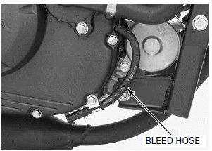
Check for signs of seal leakage.
If water leaks through the bleed hose, replace the mechanical seal.
If oil leaks through the bleed hose, replace the oil seal.
A small amount of "weeping" from the bleed hose is normal.
REMOVAL/DISASSEMBLY
Drain the coolant.
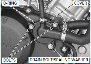
Remove the bolts, drain bolt, sealing washer, water pump cover and O-ring.
Remove the right crankcase cover.
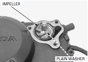
Hold the water pump shaft and remove the impeller and plain washer.
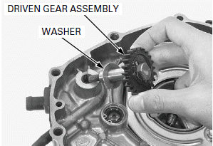
Remove the water pump driven gear assembly and washer from the right crankcase cover and disassemble them.
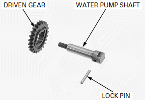
Check the water pump driven gear, water pump shaft and lock pin for wear or damage, replace them if necessary.
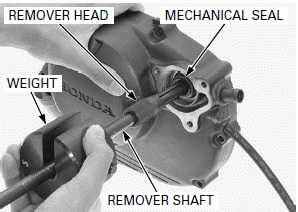
Remove the mechanical seal using the special tools.
TOOLS:
Bearing remover head, 14 mm 07WMC-KFG0100
Remover weight 07741-0010201
Bearing remover shaft 07936-KC10100
Remove the oil seal.
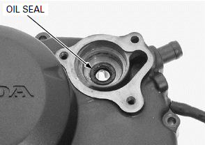
ASSEMBLY/INSTALLATION
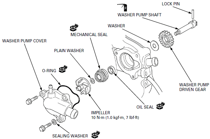
Install a new oil seal to the right crankcase cover.
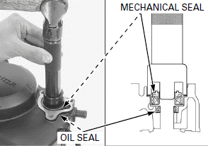
Be careful not to damage the mechanical seal lips.
Set and drive in a new mechanical seal using the special tool as shown.
TOOLS:
Driver 07749-0010000
Oil seal driver attachment, 36 mm 07945-4150400
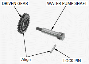
Install the lock pin to the water pump shaft, then install the water pump driven gear aligning the driven gear groove with the lock pin.
Install the washer to the water pump shaft.
Apply engine oil to the water pump shaft outer surface.
Install the water pump driven gear assembly into the right crankcase cover.
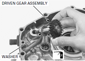
Install the plain washer and impeller to the water pump shaft.
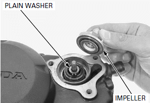
Hold the water pump shaft and tighten the water pump impeller to the specified torque.
TORQUE: 10 N-m (1.0 kgf-m, 7 lbf-ft)
Install the right crankcase cover.
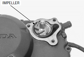
Install a new O-ring to the water pump cover.
Install the water pump cover.
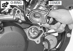
Install and tighten the bolts, drain bolt and new sealing washer securely.
Fill the recommended coolant mixture to the filler neck and bleed the air.
RADIATOR RESERVE TANK
REMOVAL/INSTALLATION
Remove the following:
- Rear cowl
- Air cleaner housing
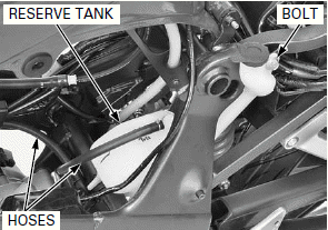
Drain the coolant from the reserve tank.
Remove the bolt and reserve tank.
Disconnect the overflow and siphon hoses from the reserve tank.
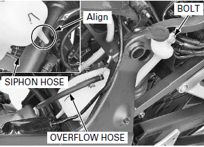
Connect the overflow and siphon hoses to the reserve tank.
Route the hoses properly.
Install the reserve tank to the frame, aligning the tab of the reserve tank with slit of the frame.
Install and tighten the bolt.
Install the following:
- Air cleaner housing
- Rear cowl
FAN CONTROL RELAY
INSPECTION
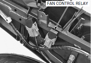
Remove the rear cowl.
Remove the fan control relay.
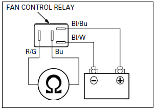
Connect a ohmmeter to the fan control relay connector terminals.
Connect a 12 V battery to the fan control relay connector terminals as shown.
There should be continuity only when 12 V battery is connected.
If there is no continuity only when the 12 V battery is connected, replace the fan control relay.
See also:
 Honda CBR125RW - Service manual > ECT Sensor
REMOVAL/INSTALLATION Drain the coolant. Lift and support the fuel tank. Replace the ECT sensor while the engine is cold. Disconnect the ECT sensor 3P (Gray) connector.
 Honda CBR125RW - Service manual > Engine Removal/Installation
COMPONENT LOCATION

 BMW G310GS
 Honda CBR125RW
 Husqvarna 401 Vitpilen
 KTM 890 Duke R
 Mash Dirt Track 650
 Peugeot Kisbee
 Yamaha Tracer MT-09
 Honda CBR125RW
 Peugeot Kisbee
 Yamaha Tracer MT-09