 Honda CBR125RW - Service manual > ECT Sensor
REMOVAL/INSTALLATION
Drain the coolant.
Lift and support the fuel tank.
Replace the ECT sensor while the engine is cold.
Disconnect the ECT sensor 3P (Gray) connector.
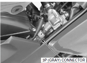
Remove the ECT sensor and sealing washer.
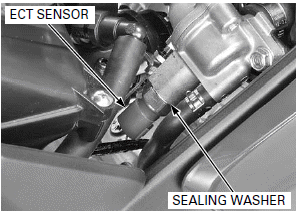
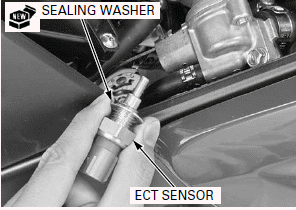
Always replace a sealing washer with a new one.
Install a new sealing washer onto the ECT sensor and install them.
Tighten the ECT sensor to the specified torque.
TORQUE: 24.5 N-m (2.5 kgf-m, 18 lbf-ft)
Connect the ECT sensor 3P (Gray) connector.
Remove the suitable support and close the fuel tank.
Fill the cooling system with recommended coolant.
BANK ANGLE SENSOR
REMOVAL/INSTALLATION
Remove the upper cowl.
Remove the mounting screw/washers, collars and bank angle sensor.
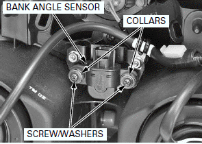
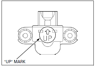
Install the bank angle sensor with its "UP" mark facing up.
Install the bank angle sensor, collars and mounting screw/washers.
Tighten the mounting screws to the specified torque.
TORQUE: 1.2 N-m (0.1 kgf-m, 0.9 lbf-ft)
Install the upper cowl.
INSPECTION WITH HDS POCKET TESTER
Connect the HDS pocket tester.
Remove the bank angle sensor.
Connect the bank angle sensor 3P connector.
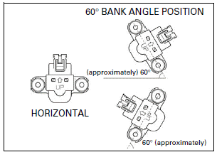
Place the bank angle sensor horizontal as shown.
Turn the ignition switch ON (and engine stop switch " ":
CM and U type).
Read the voltage with the HDS pocket tester.
Standard: 3.6 - 4.4 V
Incline the bank angle sensor approximately 60º to the left or right with
keeping the ignition switch ON (and engine stop switch " ":
CM and U type).
Read the voltage with HDS pocket tester.
Standard: 0.7 - 1.3 V
- If you repeat this test, first turn the ignition switch OFF, then turn
the ignition switch ON (and engine stop switch "
 ":
CM and U type).
INSPECTION WITH ECM TEST HARNESS
Connect the ECM test harness.
Remove the bank angle sensor.
Connect the bank angle sensor 3P connector.
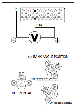
Place the bank angle sensor horizontal as shown.
Turn the ignition switch ON (and engine stop switch " ":
CM and U type).
Measure the output voltage with the ECM test harness at its terminals.
Connection: 26 (+) - 4 (-)
Standard: 3.6 - 4.4 V
Incline the bank angle sensor approximately 60º to the left or right with
keeping the ignition switch ON (and engine stop switch " ":
CM and U type).
Measure the output voltage with ECM test harness at its terminals.
Connection: 26 (+) - 4 (-)
Standard: 0.7 - 1.3 V
- If you repeat this test, first turn the ignition switch OFF, then turn
the ignition switch ON (and engine stop switch "
 ":
CM and U type).
ECM
REMOVAL/ INSTALLATION
Lift and support the fuel tank.
Open the rubber sheet.
Turn the ignition switch OFF.
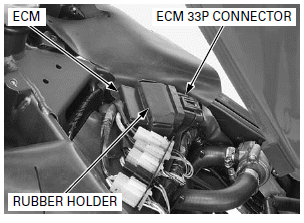
Disconnect the ECM 33P connector.
Remove the rubber holder and ECM.
Remove the ECM from the rubber holder.
Install the ECM to the rubber holder install them to the frame.
Connect the ECM 33P connector.
Close the rubber sheet.
Remove the suitable support and close the fuel tank.
ECM POWER/GROUND LINE INSPECTION
ENGINE DOES NOT START (No DTC and MIL blinking)
1. ECM Power Input Voltage Inspection
- Before starting the inspection, check for loose or poor contact on the ECM 33P connector and recheck the MIL blinking.
Lift and support the fuel tank.
Open the rubber sheet.
Disconnect the ECM 33P connector.
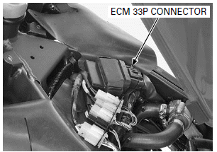
Turn the ignition switch ON (and engine stop switch " ":
CM and U type).
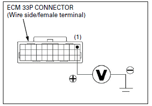
Measure the voltage at the ECM 33P connector of the wire side and ground.
TOOL: Test probe 07ZAJ-RDJA110
Connection: 1 (Black/white) (+) - Ground (-)
Standard: Battery voltage
Does the standard voltage exist?
YES - GO TO STEP 2.
NO -
- Open or short circuit in Black/white wire
- Faulty ignition switch
- Blown main or sub fuse
- Faulty engine stop switch (CM and U type)
2. ECM Ground Line Inspection
Turn the ignition switch OFF.
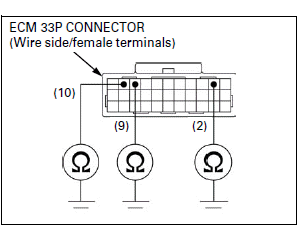
Check the continuities between the ECM 33P connector of the wire side and ground.
TOOL: Test probe 07ZAJ-RDJA110
Connection:
2 (Green/black) - Ground
9 (Green) - Ground
10 (Green) - Ground
Is there continuity?
YES - Replace the ECM with a known good one, and recheck.
NO -
- Open circuit in Green/black wire
- Open circuit in Green wires
O2 SENSOR

- Do not get grease, oil or other materials in the O2 sensor air hole.
- The O2 sensor may be damaged if dropped.
Replace it with a new one, if dropped.
- If the O2 sensor cap is disconnected, replace the O2 sensor cord with a new one, do not reuse O2 sensor cord.
REMOVAL
- Handle the O2 sensor with care.
- Do not service the O2 sensor while it is hot.
Remove the right middle cowl.
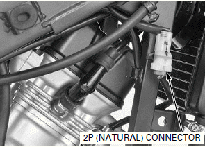
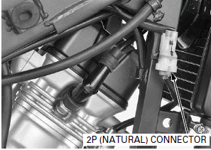
Disconnect the O2 sensor 2P (natural) connector.
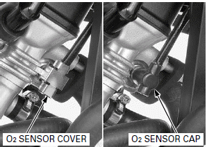
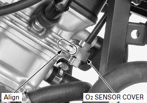
Remove the O2 sensor cover and disconnect the O2 sensor cap.
Discard the O2 sensor cord.
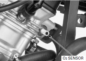
Remove the O2 sensor.
INSTALLATION
- Do not use an impact wrench while removing or installing the O2 sensor, or it may be damaged.
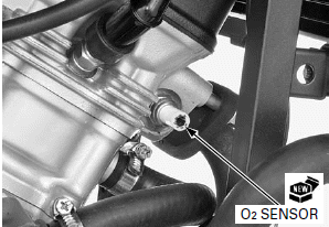
Install and hand tighten a new O2 sensor onto the cylinder head.
Tighten the O2 sensor to the specified torque.
TORQUE: 25 N-m (2.5 kgf-m, 18 lbf-ft)
Connect the O2 sensor cap by installing a new O2 sensor cord.

- Take care not to tilt the O2 sensor cap when connecting the cap to the O2 sensor.
- Do not turn the O2 sensor cap, after connecting it.
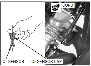
Install the O2 sensor cover aligning its tab with between the fins of the cylinder head.
Install the right middle cowl.
Connect the O2 sensor 2P (natural) connector.
See also:
 Honda CBR125RW - Service manual > Injector
QUICK CONNECT FITTING REMOVAL Always clean around the injector before the injector removal to prevent dirt and debris from entering the injector passage.
 Honda CBR125RW - Service manual > Cooling System
SYSTEM FLOW PATTERN RESERVE TANK SIPHON HOSE THERMOSTAT WATER HOSES RADIATOR WATER PUMP

 BMW G310GS
 Honda CBR125RW
 Husqvarna 401 Vitpilen
 KTM 890 Duke R
 Mash Dirt Track 650
 Peugeot Kisbee
 Yamaha Tracer MT-09
 Honda CBR125RW
 Peugeot Kisbee
 Yamaha Tracer MT-09