 Honda CBR125RW - Service manual > Fuel System (PGM-FI)
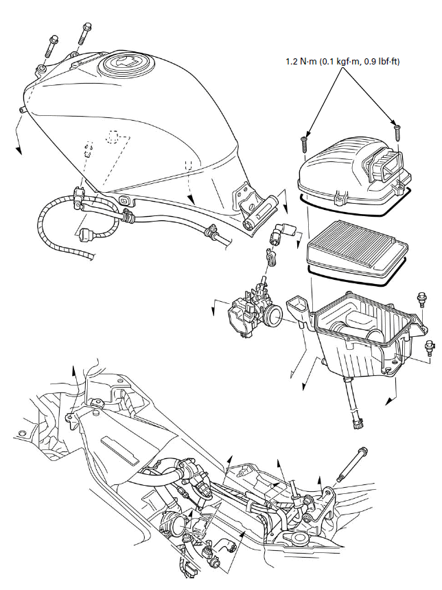
COMPONENT LOCATION

SERVICE INFORMATION
GENERAL
- Work in a well ventilated area. Smoking or allowing flames or sparks in the work area or where gasoline is stored can cause a fire or explosion.
- Before disconnecting the fuel feed hose, relieve fuel pressure from the system by disconnecting the quick connect fitting at the fuel pump.
- Bending or twisting the control cables will impair smooth operation and could cause the cables to stick or bind, resulting in loss of vehicle control.
- Do not apply commercially available carburetor cleaners to the inside of the throttle bore.
- Do not snap the throttle valve from full open to full close after the throttle cable has been removed. It may cause incorrect idle operation.
- Seal the intake ports with tape or a clean cloth to keep dirt and debris from entering the engine after the throttle body has been removed.
- Do not damage the throttle body. It may cause incorrect throttle valve operation.
- Prevent dirt and debris from entering the throttle bore and air passages after the throttle body has been removed. Clean them using a compressed air if necessary.
- The throttle body is factory pre-set. Do not disassemble in a way other than shown in this manual.
- Do not loosen or tighten the white painted nut and screw of the throttle body. Loosening or tightening them can cause throttle valve and idle control failure.
- The parts of the throttle body not shown in this manual should not be disassembled.
- Always replace the packing when the fuel pump is removed.
- A faulty PGM-FI system is often related to poorly connected or corroded connectors. Check those connections before proceeding.
- The PGM-FI system is equipped with the Self-Diagnostic System described. If the MIL blinks, follow the Self-Diagnostic Procedures to remedy the problem.
- When checking the PGM-FI system, always follow the steps in the troubleshooting table.
- The PGM-FI system is provided with fail-safe function to secure a
minimum running capability even when there is any trouble in the system.
When any abnormality is detected by the self-diagnosis function, running
capability is secured by making use of the numerical values of a situation
preset in advance in the simulated program map.
It must be remembered, however, that when any abnormality is detected in injector, the fail-safe function stops the engine to protect it from damage.
- When disassembling the PGM-FI system parts, note the location of the O-rings. Replace them with new ones upon reassembly.
- Use a digital tester for PGM-FI system inspection.
SPECIFICATIONS

TORQUE VALUES
Bank angle sensor mounting screw 1.2 N-m (0.1 kgf-m, 0.9 lbf-ft)
ECT sensor 24.5 N-m (2.5 kgf-m, 18 lbf-ft)
Fuel pump setting plate nut - For tightening sequence
Injector joint mounting bolt 5.1 N-m (0.5 kgf-m, 3.8 lbf-ft)
O2 sensor 25 N-m (2.5 kgf-m, 18 lbf-ft)
Sensor unit torx screw 3.4 N-m (0.3 kgf-m, 2.5 lbf-ft)
IACV setting plate torx screw 2.1 N-m (0.2 kgf-m, 1.5 lbf-ft)
Throttle cable stay screw 3.4 N-m (0.3 kgf-m, 2.5 lbf-ft)
Insulator band screw -
Air cleaner cover screw 1.2 N-m (0.1 kgf-m, 0.9 lbf-ft)
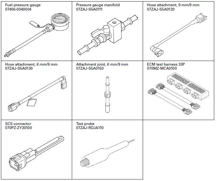
TOOLS

See also:
 Honda CBR125RW - Service manual > Lubrication System
LUBRICATION SYSTEM DIAGRAM CAMSHAFT ROCKER ARM CRANKSHAFT COUNTERSHAFT MAINSHAFT OIL STRAINER SCREEN OIL PUMP
 Honda CBR125RW - Service manual > PGM-FI
PGM-FI SYMPTOM TROUBLESHOOTING When the motorcycle has one of these symptoms, check the DTC or MIL blinking, refer to the DTC index and begin the appropriate troubleshooting procedure. If there are no DTC/MIL blinking stored in the ECM memory, do the diagnostic procedure for the symptom, in sequence listed below, until you find cause.

 BMW G310GS
 Honda CBR125RW
 Husqvarna 401 Vitpilen
 KTM 890 Duke R
 Mash Dirt Track 650
 Peugeot Kisbee
 Yamaha Tracer MT-09
 Honda CBR125RW
 Peugeot Kisbee
 Yamaha Tracer MT-09