 Honda CBR125RW - Service manual > Lubrication System
LUBRICATION SYSTEM DIAGRAM
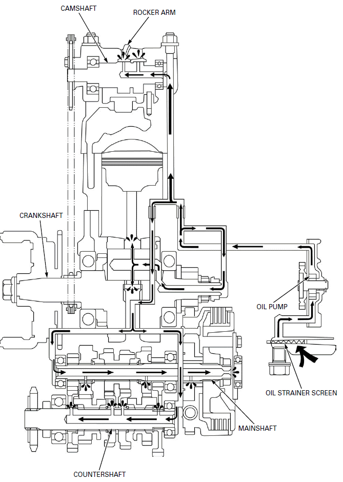
- CAMSHAFT
- ROCKER ARM
- CRANKSHAFT
- COUNTERSHAFT
- MAINSHAFT
- OIL STRAINER SCREEN
- OIL PUMP
SERVICE INFORMATION
GENERAL

Used engine oil may cause skin cancer if repeatedly left in contact with the skin for prolonged periods. Although this is unlikely unless you handle used oil on a daily basis, it is still advisable to thoroughly wash your hands with soap and water as soon as possible after handling used oil.
- The oil pump can be serviced with the engine installed in the frame.
- The service procedures in this section must be performed with the engine oil drained.
- When removing and installing the oil pump, use care not to allow dust or dirt to enter the engine.
- If any portion of the oil pump is worn beyond the specified service limit, replace the oil pump as an assembly.
- After the oil pump has been installed, check that there are no oil leaks.
- Refer to the following:
- engine oil level check.
- engine oil change
SPECIFICATIONS
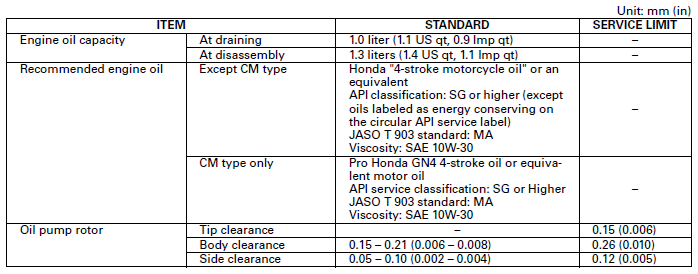
TORQUE VALUE
Oil pump assembly bolt 5.0 N-m (0.5 kgf-m, 3.7 lbf-ft)
TROUBLESHOOTING
Engine oil level too low, high oil consumption
- Oil consumption
- External oil leaks
- Worn valve guide or stem seal
- Worn piston rings
- Improperly installed piston rings
- Worn cylinder
Engine oil contamination
- Oil not changed often enough
- Worn valve guide or stem seal
- Worn piston rings
- Improperly installed piston rings
- From coolant mixing with oil
- Faulty head gasket
- Water leak in crankcase
OIL PUMP
REMOVAL
Remove the right crankcase cover.
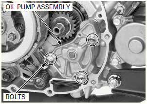
Remove the mounting bolts and oil pump assembly.
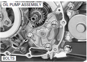
DISASSEMBLY
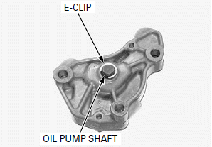
Remove the E-clip from the oil pump shaft.
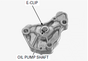
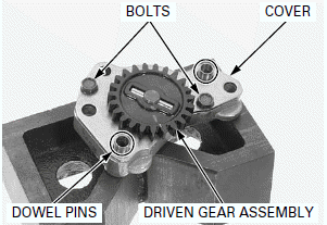
Remove the oil pump driven gear assembly and disassemble them.
Remove the dowel pins, bolts and oil pump cover.
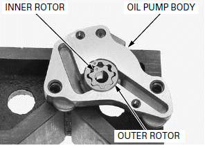
Remove the inner and outer rotors from the oil pump body.
INSPECTION
OIL PUMP DRIVEN GEAR/OIL PUMP SHAFT/LOCK PIN
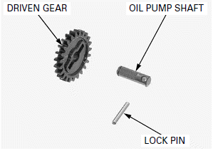
Check the oil pump driven gear, oil pump shaft and lock pin for wear or damage, replace them if necessary.
OIL SEAL
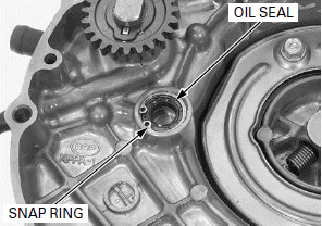
Check the oil seal for damage or deterioration, replace it if necessary.
After installing a snap ring, always rotate it in its groove to be sure it is fully seated.
Check that the washer and snap ring are installed in the left crankcase cover securely.
OIL PUMP
NOTE:
Measure each clearance at several points and use the largest reading to compare the service limit.
If any portion of the oil pump is worn beyond the specified service limit, replace the oil pump as an assembly.
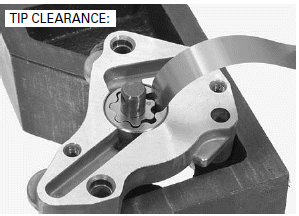
Temporarily install the outer rotor, inner rotor and oil pump shaft into the oil pump body.
Measure the tip clearance.
SERVICE LIMIT: 0.15 mm (0.006 in)
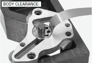
Measure the body clearance.
SERVICE LIMIT: 0.26 mm (0.010 in)
Remove the oil pump shaft.
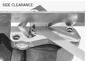
Measure the side clearance using a straight edge and feeler gauge.
SERVICE LIMIT: 0.12 mm (0.005 in)
ASSEMBLY
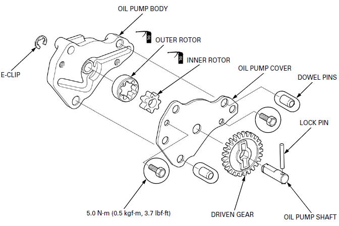
Apply engine oil to the inner and outer rotors entire surface.
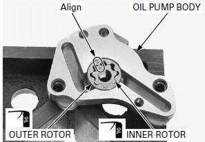
Install the oil pump inner and outer rotors in to the oil pump body with aligning the both punch marks.
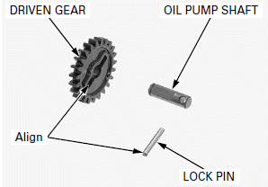
Install the lock pin into the oil pump shaft, then install the oil pump driven gear aligning the oil pump driven gear groove with lock pin.
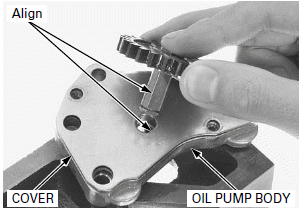
Install the oil pump cover.
Install the oil pump driven gear assembly into the oil pump body aligning the flats of the oil pump shaft and inner rotor.
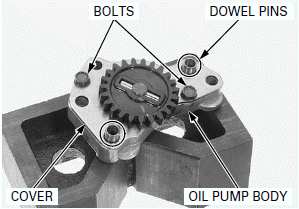
Install the dowel pins in to the oil pump body.
Install and tighten the bolts to the specified torque.
TORQUE: 5.0 N-m (0.5 kgf-m, 3.7 lbf-ft)
Set the flat surface of the E-clip is upward.
Install the E-clip to the oil pump shaft.
INSTALLATION
Install the oil pump assembly.
Install and tighten the mounting bolts securely.
Install the right crankcase cover.
See also:
 Honda CBR125RW - Service manual > Fuel System (PGM-FI)
COMPONENT LOCATION SERVICE INFORMATION

 BMW G310GS
 Honda CBR125RW
 Husqvarna 401 Vitpilen
 KTM 890 Duke R
 Mash Dirt Track 650
 Peugeot Kisbee
 Yamaha Tracer MT-09
 Honda CBR125RW
 Peugeot Kisbee
 Yamaha Tracer MT-09