 Honda CBR125RW - Service manual > Fuel
FUEL LINE INSPECTION
FUEL PRESSURE RELIEVING/QUICK CONNECT FITTING REMOVAL
- Do not bend or twist fuel feed hose.
- Before disconnecting fuel feed hose, relieve pressure from the system as follows.
1. Turn the ignition switch OFF.
2. Lift and support the fuel tank.
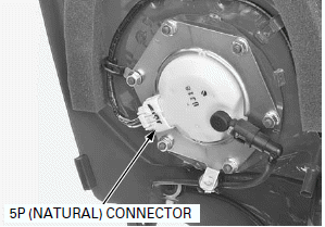
3. Disconnect the fuel pump 5P (Natural) connector.
Turn the ignition switch ON (and engine stop switch " ":
CM and U type).
4. Start the engine, and let it idle until the engine stalls.
5. Turn the ignition switch OFF.
6. Disconnect the battery negative (-) cable.
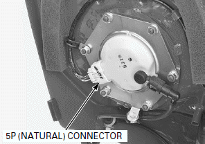
7. Check the fuel quick connect fitting for dirt, and clean if necessary.
Place a shop towel over the quick connect fitting.
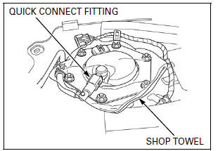
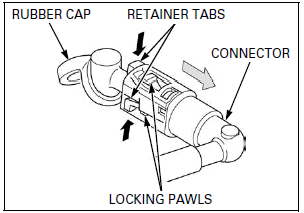
8. Pull and release the rubber cap from the retainer.
9. Hold the connector with one hand and squeeze the retainer tabs with the other hand to release them from the locking pawls.
Pull the connector off and remove the retainer.
NOTE:
- Absorb the remaining fuel in the fuel feed hose from flowing out with a shop towel.
- Be careful not to damage the hose or other parts.
- Do not use tools.
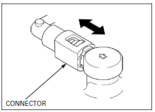
- If the connector does not move, keep the retainer tabs pressed down, and alternately pull and push the connector until it comes off easily.
10.To prevent damage and keep foreign matter out, cover the disconnected connector and pipe end with the plastic bags.
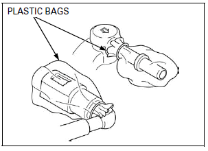
QUICK CONNECT FITTING INSTALLATION
- Always replace the retainer of the quick connect fitting when the fuel feed hose is disconnected.
- If any retainer needs replacing, use the same manufacturer's retainer as the ones being removed (The various manufactures feature different retainer specifications).
- If any damage or cut-out on the rubber cap or connector damper, replace it with a new one.
- Do not bent or twist fuel feed hose.
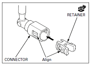
1. Insert a new retainer into the connector.
NOTE:
- Align new retainer locking pawls with the connector grooves.
2. Set the rubber cap as shown.
Then press the quick connect fitting onto the pipe until both retainer pawls lock with a "CLICK".
NOTE:
- Align the quick connect fitting with the pipe.
If it is hard to connect, put a small amount of engine oil on the pipe end.
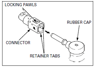
3. Make sure the connection is secure and that the pawls are firmly locked into place; check visually and by pulling the connector.
4. Make sure the rubber cap is in place (between the retainer tabs).
5. Connect the fuel pump 5P (Natural) connector.
Connect the battery negative (-) cable.
6. Turn the ignition switch ON (and engine stop switch " ":
CM and U type).
NOTE:
- Do not start the engine.
The fuel pump will run for about 2 seconds, and fuel pressure will rise.
Repeat 2 or 3 times, and check that there is no leakage in the fuel supply system.
Turn the ignition switch OFF.
Remove the suitable support and close the fuel tank.
FUEL PRESSURE TEST
Relieve the fuel pressure and disconnect the quick connect fitting.
Attach the fuel pressure gauge, attachments and manifold.
TOOLS:
- Fuel pressure gauge 07406-0040004
- Pressure gauge manifold 07ZAJ-S5A0111
- Hose attachment, 9 mm/9 mm 07ZAJ-S5A0120
- Hose attachment, 6 mm/9 mm 07ZAJ-S5A0130
- Attachment joint, 6 mm/9 mm 07ZAJ-S5A0150
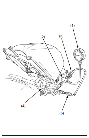
Temporarily connect the battery negative (-) cable and fuel pump 5P connector.
Turn the ignition switch ON (and engine stop switch " ":
CM and U type).
Start the engine and let it idle.
Read the fuel pressure.
Standard: 294 kPa (3.0 kgf/cm2, 43 psi)
If the fuel pressure is higher than specified, replace the fuel pump assembly.
If the fuel pressure is lower than specified, inspect the following:
- Fuel line leaking
- Pinched or clogged fuel feed hose or fuel tank breather hose
- Fuel pump unit
- Clogged fuel filter (Assembly of the fuel pump unit)
After inspection, relieve the fuel pressure.
Remove the fuel pressure gauge, attachment and manifold from the fuel pump.
Connect the quick connect fitting.
FUEL FLOW INSPECTION
Relieve the fuel pressure and disconnect the quick connect fitting.
Wipe off spilled out gasoline.
Connect the special tool to the fuel pump joint.
TOOL: Hose attachment, 6 mm/9 mm 07ZAJ-S5A0130
Place the end of the hose into an approved gasoline container.
Temporarily connect the battery negative (-) cable and fuel pump 5P connector.
Turn the ignition switch ON (and engine stop switch " ":
CM and U type).
Measure the amount of fuel flow.
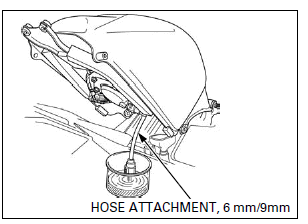
NOTE:
- The fuel pump operates for 2 seconds. Repeat 5 times so that the total measuring time.
- Return fuel to the fuel tank when the first fuel is flowed.
Amount of fuel flow: 13.9 cm3 (0.47 US oz, 0.49 Imp oz) minimum/10 seconds at 12 V
If fuel flow is less than specified, inspect the following:
- Fuel pump unit.
- Clogged fuel filter (Assembly of the fuel pump unit)
Connect the quick connect fitting.
FUEL PUMP UNIT
INSPECTION
Turn the ignition switch ON (and engine stop switch " ":
CM and U type) and confirm that the fuel pump operates for 2 seconds.
If the fuel pump does not operate, inspect as follows: Turn the ignition switch OFF.
Lift and support the fuel tank.
Disconnect the fuel pump 5P (Natural) connector.
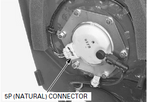
Turn the ignition switch ON (and engine stop switch " ":
CM and U type).
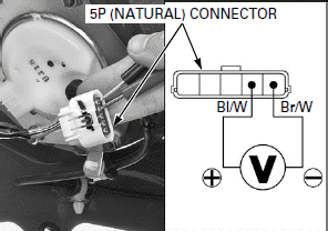
Measure the voltage at the fuel pump 5P (Natural) connector terminals of the wire side.
Connection: Black/white (+) - Brown/white (-)
Standard: Battery voltage
There should be standard voltage for a few seconds.
If there is standard voltage, replace the fuel pump unit.
If there is no standard voltage, inspect the following:
- Main fuse 30 A
- Sub fuse 10 A
- Ignition switch
- Engine stop switch (CM and U type)
- Open circuit in Black/white or Brown/white wire
- ECM
REMOVAL
- Do not disassemble the fuel pump.
Clean around the fuel pump.
Relieve the fuel pressure and disconnect the quick connect fitting.
Remove the fuel tank.
Loosen the fuel pump setting plate nuts in a crisscross pattern in 2 or 3 steps.
Remove the nuts and clamp.
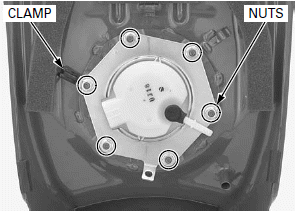
Be careful not to damage the fuel level sensor float arm.
Remove the setting plate, fuel pump unit and packing.
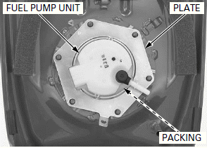
INSPECTION
Check the fuel pump unit for wear or damage, replace it if necessary.
Check the fuel filter for wear or damage.
Apply engine oil to the fuel tank contacting area of the fuel pump.
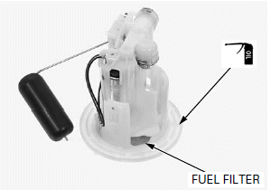
INSTALLATION
Always replace the packing with a new one. Be careful not to pinch the dirt and debris between the fuel pump unit and packing.
Install a new packing onto the fuel pump unit.
Be careful not to damage the fuel level sensor float arm.
Install the fuel pump unit into the fuel tank.
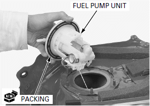
When installing the setting plate onto the fuel pump unit, align the following:
- Slots of the fuel pump setting plate and tabs of the fuel pump unit
- "
 "
marks of the fuel pump setting plate and fuel tank
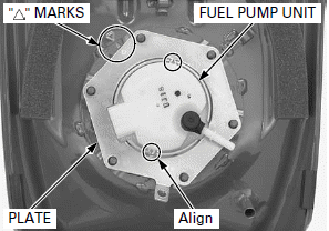
Install the nuts and clamp.
Tighten the fuel pump nuts to the specified torque in the specified sequence as shown.
TORQUE: 12 N-m (1.2 kgf-m, 9 lbf-ft)
Route the pump unit wire properly.
Connect the quick connect fitting.
Install the fuel tank.
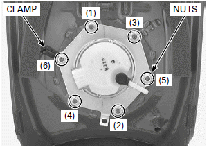
FUEL TANK
REMOVAL/INSTALLATION
Relieve the fuel pressure and disconnect the quick connect fitting.
Release the fuel feed hose and fuel pump wire from the clamps.
Disconnect the fuel tank breather hose.
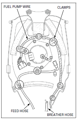
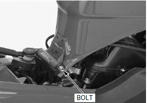
Remove the bolt and fuel tank.
Install the fuel tank in the reverse order of removal.
Route the hose and wire properly.
Connect the quick connect fitting.
See also:
 Honda CBR125RW - Service manual > MIL Troubleshooting
MIL 1 BLINK (MAP SENSOR) 1. Sensor Unit Power Line Inspection Check the sensor unit power line inspection. Is the sensor unit power line normal?
 Honda CBR125RW - Service manual > Air Cleaner Housing
REMOVAL/INSTALLATION Remove the air cleaner element. Disconnect the crankcase breather hose.

 BMW G310GS
 Honda CBR125RW
 Husqvarna 401 Vitpilen
 KTM 890 Duke R
 Mash Dirt Track 650
 Peugeot Kisbee
 Yamaha Tracer MT-09
 Honda CBR125RW
 Peugeot Kisbee
 Yamaha Tracer MT-09