 Honda CBR125RW - Service manual > MIL Troubleshooting
MIL 1 BLINK (MAP SENSOR)
1. Sensor Unit Power Line Inspection
Check the sensor unit power line inspection.
Is the sensor unit power line normal?
YES - GO TO STEP 2.
NO - Replace or repair of the abnormal circuit.
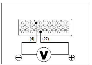
2. MAP Sensor Output Voltage Inspection
Turn the ignition switch ON (and engine stop switch " ":
CM and U type).
":
CM and U type).
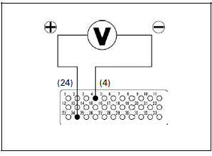
Measure the voltage at the test harness terminals.
Connection: 27 (+) - 4 (-)
Standard: 2.6 - 3.2 V (20ºC/68ºF)
Is the voltage within 2.6 - 3.2 V (20ºC/68ºF)?
YES -
- Intermittent failure
- Loose or poor contact on the ECM connector
NO -
- About 5 V: GO TO STEP 3.
- About 0 V: GO TO STEP 4.
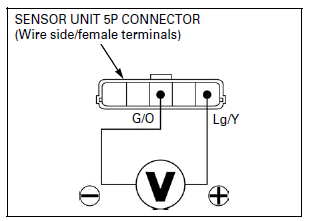
3. MAP Sensor Output Line Open Circuit Inspection 1
Turn the ignition switch OFF.
Disconnect the sensor unit 5P connector.
Turn the ignition switch ON (and engine stop switch "":
CM and U type).
Measure the voltage at the sensor unit 5P connector of the wire side.
Connection: Light green/yellow (+) - Green/orange (-)
Standard: 3.80 - 5.25 V
Is the voltage within 3.80 - 5.25 V?
YES - Faulty sensor unit (MAP sensor)
NO - Open circuit in Light green/yellow wire
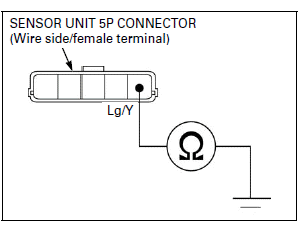
4. MAP Sensor Output Line Short Circuit Inspection
Turn the ignition switch OFF.
Disconnect the sensor unit 5P connector.
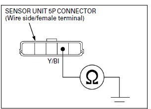
Check for continuity between the sensor unit 5P connector terminal of the wire side and ground.
Connection: Light green/yellow - Ground
Is there continuity?
YES - Short circuit in Light green/yellow wire
NO - GO TO STEP 5.
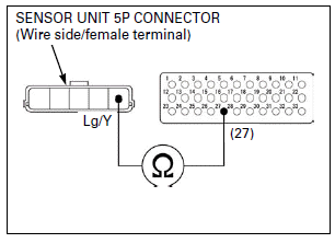
5. MAP Sensor Output Line Open Circuit Inspection 2
Check the continuity between the ECM test harness and sensor unit 5P connector of the wire side.
Connection: 27 - Light green/yellow
Is there continuity?
YES - Faulty sensor unit (MAP sensor)
NO - Open circuit in Light green/yellow wire
MIL 7 BLINKS (ECT SENSOR)
- Before starting the inspection, check for loose or poor contact on the ECT sensor 3P connector and recheck the MIL blinking.
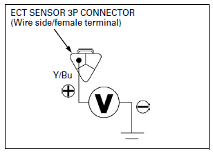
1. ECT Sensor Input Voltage Inspection
Turn the ignition switch OFF.
Disconnect the ECT sensor 3P connector.
Turn the ignition switch ON (and engine stop switch "":
CM and U type).
Measure the voltage at the ECT sensor connector of the wire side and ground.
Connection:
Yellow/blue (+) - Ground (-)
Standard: 4.75 - 5.25 V
Is the voltage within 4.75 - 5.25 V?
YES - GO TO STEP 3.
NO - GO TO STEP 2.
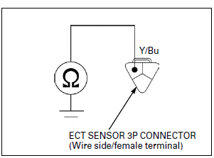
2. ECT Sensor Short Circuit Inspection
Turn the ignition switch OFF.
Check for continuity between the ECT sensor connector of the wire side and ground.
Connection: Yellow/blue - Ground
Is there continuity?
YES - Short circuit in Yellow/blue wire
NO - GO TO STEP 3.
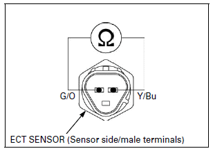
3. ECT Sensor Resistance Inspection
Turn the ignition switch OFF.
Measure the resistance at the ECT sensor terminals.
Connection: Yellow/blue - Green/orange
Standard: 2.3 - 2.6 kΩ (20ºC/68ºF)
Is the resistance within 2.3 - 2.6 kΩ (20ºC/68ºF)?
YES - GO TO STEP 4.
NO - Faulty ECT sensor
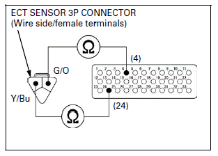
4. ECT Sensor Open Circuit Inspection
Connect the ECM test harness to ECM 33P connector.
Check the continuities between the ECM test harness and ECT 3P sensor connector of the wire side.
Connection:
24 - Yellow/blue
4 - Green/orange
Are there continuities?
YES - GO TO STEP 5.
NO -
- Open circuit in Yellow/blue wire
- Open circuit in Green/orange wire
5. ECT Sensor Output Voltage Inspection
Connect the ECT sensor 3P connector.
Turn the ignition switch ON (and engine stop switch "":
CM and U type).
Measure the voltage at the ECM test harness terminals.
Connection: 24 (+) - 4 (-)
Standard: 2.7 - 3.1 V (20ºC/68ºF)
Is the voltage within 2.7 - 3.1 V (20ºC/68ºF)?
YES -
- Loose or poor contact on the ECM connector
- Intermittent failure
NO - Replace the ECM with a known good one, and recheck.
MIL 8 BLINKS (TP SENSOR)
1. Sensor Unit Power Line Inspection
Check the sensor unit power line inspection.
Is the sensor unit power line normal?
YES - GO TO STEP 2.
NO - Replace or repair the abnormal circuit.
2. TP Sensor Output Voltage
Turn the ignition switch ON (and engine stop switch "":
CM and U type).
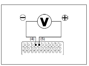
Measure the TP sensor output voltage at the ECM test harness terminals.
Connection: 5 (+) - 4 (-)
Standard:
0.29 - 0.71 V (throttle fully closed)
4.13 - 4.76 V (throttle fully opened)
Is there standard voltage?
YES -
- Intermittent failure
- Loose or poor contact on the ECM 33P connector
NO - GO TO STEP 3.
3. TP Sensor Output Line Short Circuit Inspection
Turn the ignition switch OFF.
Disconnect the sensor unit 5P connector.
Check for continuity between the sensor unit 5P connector of the wire side and ground.
Connection: Yellow/black - Ground
Is there continuity?
YES - Short circuit in Yellow/black wire
NO - GO TO STEP 4.
4. TP Sensor Voltage Input Line Open Circuit Inspection
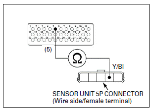
Check for continuity between the sensor unit 5P connector of the wire side and ECM test harness.
Connection: 5 - Yellow/black
Is there continuity?
YES - Faulty sensor unit (TP sensor)
NO - Open circuit in Yellow/black wire
MIL 9 BLINKS (IAT SENSOR)
1. Sensor Unit Power Line Inspection
Check the sensor unit power line inspection.
Is the sensor unit power line normal?
YES - GO TO STEP 2.
NO - Replace or repair the abnormal circuit.
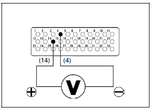
2. IAT Sensor Output Voltage Inspection 1
Turn the ignition switch ON (and engine stop switch "":
CM and U type).
Measure the voltage at the ECM test harness terminals.
Connection: 14 (+) - 4 (-)
Standard: 2.7 - 3.1 V (20ºC/68ºF)
Is the voltage within 2.7 - 3.1 V (20ºC/68ºF)?
YES -
- Intermittent failure
- Loose or poor contact on the ECM 33P connector
NO - GO TO STEP 3.
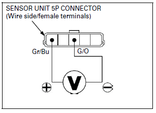
3. IAT Sensor Output Voltage Inspection 2
Turn the ignition switch OFF.
Disconnect the sensor unit 5P connector.
Turn the ignition switch ON (and engine stop switch "":
CM and U type).
Measure the voltage at the sensor unit 5P connector of the wire side.
Connection: Gray/blue (+) - Green/orange (-)
Standard: 4.75 - 5.25 V
Is the voltage within 4.75 - 5.25 V?
YES - GO TO STEP 6.
NO - GO TO STEP 4.
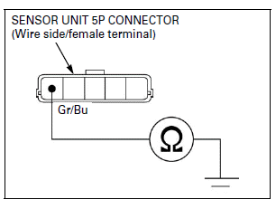
4. IAT Sensor Voltage Input Line Short Circuit Inspection
Check for continuity between the sensor unit 5P connector of the wire side and ground.
Connection: Gray/blue - Ground
Is there continuity?
YES - Short circuit in Gray/blue wire
NO - GO TO STEP 5.
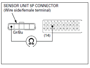
5. IAT Sensor Voltage Input Line Open Circuit Inspection
Check for continuity at the Gray/blue wire between the sensor unit 5P connector of the wire side and ECM test harness.
Connection: 14 - Gray/blue
Is there continuity?
YES - GO TO STEP 6.
NO - Open circuit in Gray/blue wire
6. IAT Sensor Resistance Inspection
Turn the ignition switch OFF.
Connect the sensor unit 5P connector.
Measure the resistance at the ECM test harness terminals (at 20ºC/68ºF).
Connection: 14 - 4
Standard: 1.13 - 1.88 kΩ (20ºC/68ºF)
Is the resistance within 1.13 - 1.88 kΩ (20ºC/ 68ºF)?
YES - Replace the ECM with a known good one, and recheck.
NO - Faulty sensor unit (IAT sensor)
MIL 12 BLINKS (INJECTOR)
- Before starting the inspection, check for loose or poor contact on the injector 2P connector and recheck the MIL blinking.
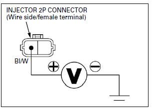
1. Injector Input Voltage Inspection
Turn the ignition switch OFF.
Disconnect the injector 2P connector.
Turn the ignition switch ON (and engine stop switch "":
CM and U type).
Measure the voltage between the injector 2P connector of the wire side and ground.
Connection: Black/white (+) - Ground (-)
Standard: Battery voltage
Does the standard voltage exist?
YES - GO TO STEP 2.
NO - Open or short circuit in Black/white wire
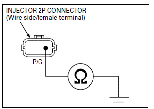
2. Injector Signal Line Short Circuit Inspection
Turn the ignition switch OFF.
Check for continuity between the injector 2P connector of the wire side and ground.
Connection: Pink/green - Ground
Is there continuity?
YES - Short circuit in Pink/green wire
NO - GO TO STEP 3.
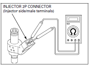
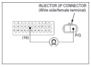
3. Injector Resistance Inspection
Measure the resistance between the injector 2P connector terminals.
Standard: 9 - 12 Ω (20ºC/68ºF)
Is the resistance within 9 - 12 Ω (20ºC/68ºF)?
YES - GO TO STEP 4.
NO - Faulty injector
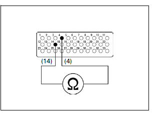
4. Injector Signal Line Open Circuit Inspection
Connect the ECM test harness to the ECM 33P connector.
Check the continuity between the ECM test harness and injector 2P connector of the wire side.
Connection: 16 - Pink/green
Is there continuity?
YES - Replace the ECM with a known good one, and recheck.
NO - Open circuit in Pink/green wire
MIL 21 BLINKS (O2 SENSOR)

- Do not get grease, oil or other materials in the O2 sensor air hole.
- Do not reuse O2 sensor cord, if the O2 sensor cap is disconnected, replace the O2 sensor cord with a new one.
- Before starting the inspection, check for loose or poor contact on the O2 sensor 2P connector or O2 sensor cap and recheck the MIL blinking.
1. O2 Sensor System Inspection
Turn the ignition switch ON (and engine stop switch "":
CM and U type).
Start the engine and warm up the engine up to coolant temperature is 80ºC (176ºF).
Test-ride the motorcycle and recheck the MIL blinking.
Does the MIL blink 21 times?
YES - GO TO STEP 2.
NO - Intermittent failure
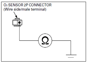
2. O2 Sensor Short Circuit Inspection
Turn the ignition switch OFF.
Disconnect the O2 sensor 2P connector.
Check for continuity between the O2 sensor 2P connector of the wire side and ground.
Connection: Black/orange - Ground
Is there continuity?
YES - Short circuit in Black/orange wire
NO - GO TO STEP 3.
3. O2 Sensor Open Circuit Inspection
Connect the ECM test harness to the ECM 33P connector.
Check the continuity between the ECM test harness and O2 sensor 2P connector of the wire side.
Connection: 3 - Black/orange
Is there continuity?
YES - GO TO STEP 4.
NO - Open circuit in Black/orange wire

4. O2 Sensor Inspection
Replace the O2 sensor and O2 sensor cord with a known good one.
Disconnect the ECM test harness and connect the ECM 33P connector.
Turn the ignition switch ON (and engine stop switch "":
CM and U type).
Start the engine and warm up the engine up to coolant temperature is 80ºC (176ºF).
Test-ride the motorcycle and recheck the MIL blinking.
Does the MIL blink 21 times?
YES - Replace the ECM with a known good one, and recheck.
NO - Faulty original O2 sensor and/or O2 sensor cord
MIL 29 BLINKS (IACV)
- Before starting the inspection, check for loose or poor contact on the IACV 4P connector and recheck the MIL blinking.
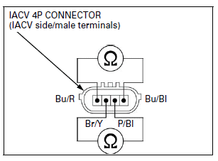
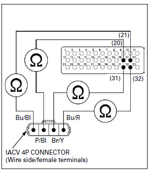
1. IACV Resistance Inspection
Turn the ignition switch OFF.
Disconnect the IACV 4P connector.
Measure the resistance at the IACV 4P connector terminals.
Connection:
Blue/black - Blue/red
Pink/black - Brown/yellow
Standard: 110 - 150 Ω (25ºC/77ºF)
Is the resistance within 110 - 150 Ω (25ºC/77ºF)?
YES - GO TO STEP 2.
NO - Faulty IACV
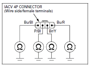
2. IACV Short Circuit Inspection
Check for continuities between the IACV 4P connector of the wire side and ground.
Connection:
Blue/black - Ground
Pink/black - Ground
Brown/yellow - Ground
Blue/red - Ground
Is there continuity?
YES -
- Short circuit in Blue/black or Pink/ black wire
- Short circuit in Brown/yellow or Blue/red wire
NO - GO TO STEP 3.
3. IACV Open Circuit Inspection
Connect the ECM test harness to ECM 33P connector.
Check the continuities between the ECM test harness and IACV 4P connector of the wire side.
Connection:
20 - Pink/black
21 - Blue/black
31 - Brown/yellow
32 - Blue/red
Is there continuity?
YES - Replace the ECM with a known good one, and recheck.
NO -
- Open circuit in Blue/black or Pink/ black wire
- Open circuit in Brown/yellow or Blue/red wire
MIL 54 BLINKS (BANK ANGLE SENSOR)
- Before starting the inspection, check for loose or poor contact on the bank angle sensor 3P connector and recheck the MIL blinking.
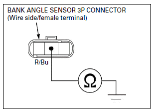
1. Bank Angle Sensor Power Input Voltage Inspection
Turn the ignition switch OFF.
Disconnect the bank angle sensor 3P connector.
Turn the ignition switch ON (and engine stop switch "":
CM and U type).
Measure the voltage at the bank angle sensor connector of the wire side.
Connection: White/red (+) - Green/orange (-)
Standard: 4.75 - 5.25 V
Is there within 4.75 - 5.25 V?
YES - GO TO STEP 4.
NO - GO TO STEP 2.

2. Bank Angle Sensor Input Voltage Line Short Circuit Inspection
Turn the ignition switch OFF.
Check the continuity between the bank angle sensor 3P connector of the wire side and ground.
Connection: White/red - Ground
Is there continuity?
YES - GO TO STEP 3.
NO - Short circuit in White/red wire
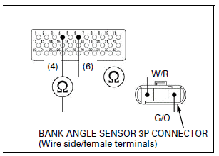
3. Bank Angle Sensor Input Voltage Line Open Circuit Inspection
Connect the ECM test harness to the ECM 33P connector.
Check the continuities between the ECM test harness and bank angle sensor 3P connector of the wire side.
Connection:
6 - White/red
4 - Green/orange
Is there continuity?
YES - Replace the ECM with a known good one, and recheck.
NO -
- Open circuit in White/red wire
- Open circuit in Green/orange wire
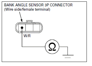
4. Bank Angle Sensor Output Line Short Circuit Inspection
Turn the ignition switch OFF.
Check the continuity between the bank angle sensor 3P connector of the wire side and ground.
Connection: Red/blue - Ground
Is there continuity?
YES - Short circuit in Red/blue wire NO - GO TO STEP 5.
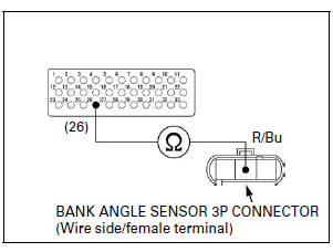
5. Bank Angle Sensor Output Line Open Circuit Inspection
Connect the ECM test harness to the ECM 33P connector.
Check the continuity between the ECM test harness and bank angle sensor 3P connector of the wire side.
Connection: 26 - Red/blue
Is there continuity?
YES - Open circuit in Red/blue wire
NO - Inspect the bank angle sensor.
MIL CIRCUIT TROUBLESHOOTING
If the engine can be started but the MIL does not come on when the ignition
switch is turned ON (and engine stop switch "":
CM and U type), check as follows: Check for the combination meter function.
NOTE:
- If it does not function, check the combination meter power input line.
- If it functions properly, check as follows:
Turn the ignition switch OFF.
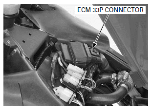
Lift and support the fuel tank.
Open the rubber sheet.
Disconnect the ECM 33P connector.
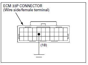
Ground the White/blue wire terminal of the wire harness side ECM 33P connector with a jumper wire.
Connection: 18 (White/black) - Ground
TOOL: Test probe 07ZAJ-RDJA110
Turn the ignition switch ON (and engine stop switch "":
CM and U type) the MIL should come on.
- If the MIL comes on, replace the ECM with a known good one and recheck the MIL indication.
- If the MIL does not come on, check for open circuit in the White/black
wire between the MIL and ECM 33P connector.
If the wire is OK, replace the combination meter.
See also:
 Honda CBR125RW - Service manual > DTC Troubleshooting
DTC 1-1 (MAP SENSOR LOW VOLTAGE) 1. MAP Sensor System Inspection Turn the ignition switch ON (and engine stop switch "": CM and U type).
Honda CBR125RW - Service manual > Fuel
FUEL LINE INSPECTION FUEL PRESSURE RELIEVING/QUICK CONNECT FITTING REMOVAL Do not bend or twist fuel feed hose. Before disconnecting fuel feed hose, relieve pressure from the system as follows.
 BMW G310GS
 Honda CBR125RW
 Husqvarna 401 Vitpilen
 KTM 890 Duke R
 Mash Dirt Track 650
 Peugeot Kisbee
 Yamaha Tracer MT-09
 Honda CBR125RW
 Peugeot Kisbee
 Yamaha Tracer MT-09