 Honda CBR125RW - Service manual > Air Cleaner Housing
REMOVAL/INSTALLATION
Remove the air cleaner element.
Disconnect the crankcase breather hose.
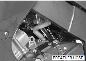
Loosen the connecting hose band screw.
Disconnect the fuel tank drain hose.
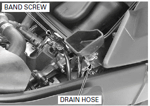
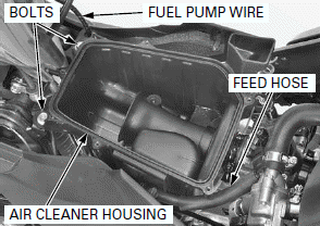
Release the fuel feed hose and fuel pump wire from the hose guides of the air cleaner housing.
Remove the bolts and air cleaner housing.
Route the hose and wire properly.
Installation is in the reverse order of removal.
THROTTLE BODY
REMOVAL
Relieve the fuel pressure and disconnect the quick connect fitting.
Remove the air cleaner housing.
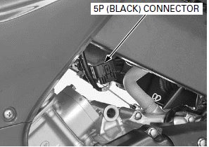
Disconnect the sensor unit 5P (Black) connector.
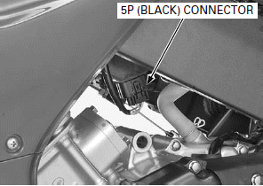
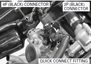
Disconnect the IACV 4P (Black) connector and injector 2P (Black) connector.
Disconnect the injector side of the quick connect fitting.
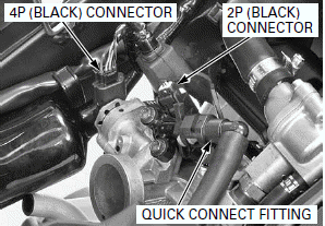
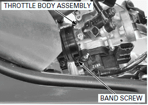
Loosen the insulator band screw (throttle body side) and remove the throttle body assembly.
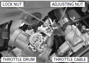
Loosen the throttle cable lock nut and adjusting nut then disconnect the throttle cable from the throttle drum and cable stay.
DISASSEMBLY

- The throttle body/sensor unit is factory pre-set.
Do not disassemble in a way other than shown in this manual.
- Do not snap the throttle valve from full open to full close after the throttle cable has been removed. It may cause incorrect idle operation.
- Do not damage the throttle body. It may cause incorrect throttle valve operation.
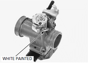
- Do not loosen or tighten the white painted nut and screw of the throttle body. Loosening or tightening it can cause throttle valve and idle control failure.
- Always clean around the throttle body before each sensor removal to prevent dirt and debris from entering the air passage.
Remove the injector.
IACV REMOVAL/INSPECTION
The IACV is installed on the throttle body and is operated by the step motor.
When the ignition switch is turned ON (and engine stop switch " ":
CM and U type), the IACV operates for a few seconds.
Check the step motor operating (beep) sound with the ignition switch turned ON
(and engine stop switch " ": CM and
U type).
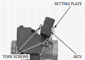
Remove the IACV setting plate torx screws and setting plate.
Remove the IACV.
Check the IACV for wear or damage.
Replace if necessary.
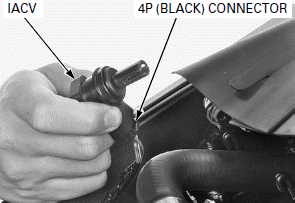
The IACV operation can be checked visually as follows:
1. Connect the IACV 4P (Black) connector.
2. Turn ignition switch ON (and engine stop switch " ":
CM and U type).
Disconnect the IACV 4P (Black) connector.
SENSOR UNIT REMOVAL
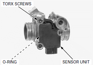
Remove the sensor unit torx screws, sensor unit and O-ring.
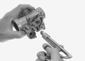
Cleaning the air passages and sensor hole with a piece of wire will damage the throttle body.
Clean the air passage of the throttle body using a compressed air.
Check the air passage for clogs.
ASSEMBLY
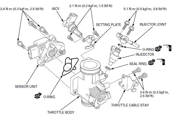
Install the injector.
SENSOR UNIT INSTALLATION
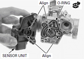
If the O-ring is not installed properly, the idle air will leaks and engine idle speed will be unstable.
Install a new O-ring to the throttle body properly.
When installing the sensor unit to the throttle body, align the following:
- Clip of the TP sensor with the boss of the throttle valve
- IAT sensor of the throttle body with the hole
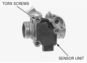
Install and tighten the sensor unit torx screws to the specified torque.
TORQUE: 3.4 N-m (0.3 kgf-m, 2.5 lbf-ft)
- Perform the throttle valve fully closed reset procedure.
IACV INSTALLATION
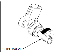
Turn the slide valve clockwise until lightly seated on IACV.
Install the IACV aligning its groove with the slide valve housing pin.
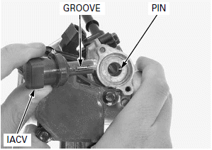
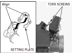
Install the setting plate while aligning the cut-out with the lug on the IACV as shown.
Install and tighten the IACV setting plate torx screws to the specified torque.
TORQUE: 2.1 N-m (0.2 kgf-m, 1.5 lbf-ft)
INSTALLATION
Connect the throttle cable to the throttle drum and throttle cable stay.
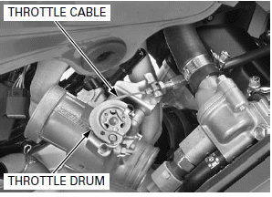
Install the throttle body assembly to the throttle body insulator by aligning the tab of the throttle body with the groove of the throttle body insulator.
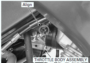
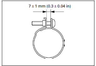
Tighten the insulator band screw so that the width between the band ends clearance is 7 +- 1 mm (0.3 +- 0.04 in).
Connect the IACV 4P (Black) connector and injector 2P (Black) connector.
Connect the injector side of the quick connect fitting.
Connect the sensor unit 5P (Black) connector.
NOTE:
If the sensor unit is removed, reset the throttle valve fully closed position.
Install the air cleaner housing.
Route the hose and wire properly.
Connect the quick connect fitting.
Adjust the throttle grip freeplay.
THROTTLE VALVE FULLY CLOSED POSITION RESET PROCEDURE
- If the sensor unit is removed, reset the throttle valve fully closed position as following.
1. Lift and support the fuel tank.
2. Clear the DTC's.
3. Turn the ignition switch OFF.
4. Remove the dummy connector.
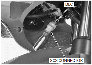
5. Short the DLC using a special tool.
TOOL: SCS connector 070PZ-ZY30100
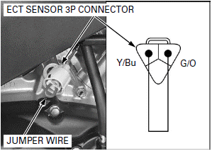
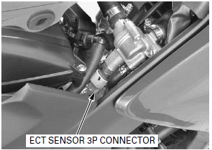
6. Disconnect the ECT sensor 3P connector.
Short the ECT sensor 3P connector terminals of the wire harness side using a jumper wire.
Connection: Yellow/blue - Green/orange
7. Turn the ignition switch ON (and engine stop switch " ":
CM and U type).
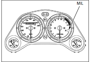
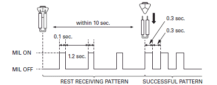
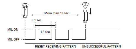
Disconnect the jumper wire while the MIL blinking (within 10 seconds).
8. After disconnection of the jumper wire, the MIL start to blinking.
9. Success pattern see below.
If the MIL begins short blink (0.3 seconds), the throttle valve fully closed position is reset.
If the MIL stays lit, the throttle valve fully closed position is not reset, repeat the reset procedure from step 2.
10.Turn the ignition switch OFF.
11.Connect the ECT sensor 3P connector.
Remove the suitable support and close the fuel tank.
See also:
 Honda CBR125RW - Service manual > Fuel
FUEL LINE INSPECTION FUEL PRESSURE RELIEVING/QUICK CONNECT FITTING REMOVAL Do not bend or twist fuel feed hose. Before disconnecting fuel feed hose, relieve pressure from the system as follows.
 Honda CBR125RW - Service manual > Injector
QUICK CONNECT FITTING REMOVAL Always clean around the injector before the injector removal to prevent dirt and debris from entering the injector passage.

 BMW G310GS
 Honda CBR125RW
 Husqvarna 401 Vitpilen
 KTM 890 Duke R
 Mash Dirt Track 650
 Peugeot Kisbee
 Yamaha Tracer MT-09
 Honda CBR125RW
 Peugeot Kisbee
 Yamaha Tracer MT-09