 Honda CBR125RW - Service manual > DTC Index
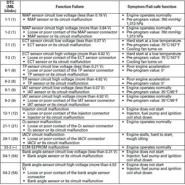
SENSOR UNIT POWER LINE INSPECTION
BEFORE DTC TROUBLESHOOTING
- When the DTC displays 1-1, 1-2, 8-1, 8-2, 9-1 and 9-2, check the following before DTC troubleshooting.
- Before starting the inspection, check for loose or poor contact on the sensor unit 5P connector and ECM 33P connector.
1. Sensor Unit Power Input Voltage Inspection
Turn the ignition switch OFF.
Disconnect the sensor unit 5P connector.
Turn the ignition switch ON (and engine stop switch " ":
CM and U type).
Measure the voltage at the wire side.
Connection: White/red (+) - Green/orange (-)
Standard: 4.75 - 5.25 V
If the voltage within 4.75 - 5.25 V?
YES - Turn the ignition switch OFF. Connect the sensor unit 5P connector and start the DTC troubleshooting.
NO - GO TO STEP 2.
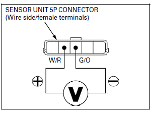
2. Sensor Unit Input Voltage Line Short Circuit Inspection
Turn the ignition switch OFF.
Check for continuity between the sensor unit 5P connector of the wire side and ground.
Connection: White/red - Ground
Is there continuity?
YES - Short circuit in White/red wire
NO - GO TO STEP 3.
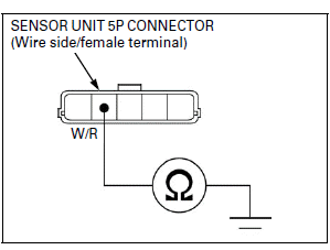
3. Sensor Unit Power Line Open Circuit Inspection
Disconnect the ECM 33P connector.
Check for continuities at the White/red and Green/orange wires between the sensor unit 5P and ECM 33P connectors.
Connection:
6 (Yellow/red) - White/red
4 (Green/orange) - Green/orange
TOOL: Test probe 07ZAJ-RDJA110
Is there continuity?
YES - Replace the ECM with a known good one, and recheck.
NO -
- Open circuit in White/red wire
- Open circuit in Green/orange wire
BEFORE MIL TROUBLESHOOTING
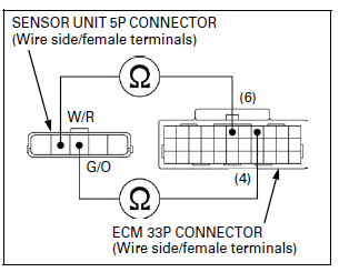
- When the MIL blinks 1, 8 and 9 times, check the following before MIL troubleshooting.
- Before starting the inspection, check for loose or poor contact on the sensor unit 5P connector and ECM 33P connector.
1. Sensor Unit Power Input Voltage Inspection 1
Turn the ignition switch OFF.
Connect the ECM test harness to the ECM 33P connector.
Turn the ignition switch ON (and engine stop switch " ":
CM and U type).
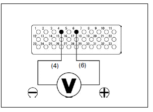
Measure the voltage at the test harness terminals.
Connection: 6 (+) - 4 (-)
Standard: 4.75 - 5.25 V
Is the voltage within 4.75 - 5.25 V?
YES - GO TO STEP 2.
NO - Replace the ECM with a known good one, and recheck.
2. Sensor Unit Power Input Voltage Inspection 2
Turn the ignition switch OFF.
Disconnect the sensor unit 5P connector.
Turn the ignition switch ON (and engine stop switch " ":
CM and U type).
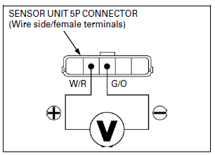
Measure the voltage at the wire side.
Connection: White/red (+) - Green/orange (-)
Standard: 4.75 - 5.25 V
If the voltage within 4.75 - 5.25 V?
YES - Turn the ignition switch OFF. Connect the sensor unit 5P connector and start the MIL troubleshooting.
NO - GO TO STEP 3.
3. Sensor Unit Input Voltage Line Short Circuit Inspection
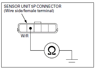
Check for continuity between the sensor unit 5P connector of the wire side and ground.
Connection: White/red - Ground
Is there continuity?
YES - Short circuit in White/red wire
NO - GO TO STEP 4.
4. Sensor Unit Input Voltage Line Open Circuit Inspection
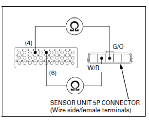
Check for continuities between the test harness and sensor unit 5P connector of the wire side.
Connection:
6 - White/red
4 - Green/orange
Is there continuity?
YES - Intermittent failure
NO -
- Open circuit in White/red wire
- Open circuit in Green/orange wire
See also:
 Honda CBR125RW - Service manual > PGM-FI
PGM-FI SYMPTOM TROUBLESHOOTING When the motorcycle has one of these symptoms, check the DTC or MIL blinking, refer to the DTC index and begin the appropriate troubleshooting procedure. If there are no DTC/MIL blinking stored in the ECM memory, do the diagnostic procedure for the symptom, in sequence listed below, until you find cause.
 Honda CBR125RW - Service manual > DTC Troubleshooting
DTC 1-1 (MAP SENSOR LOW VOLTAGE) 1. MAP Sensor System Inspection Turn the ignition switch ON (and engine stop switch "": CM and U type).

 BMW G310GS
 Honda CBR125RW
 Husqvarna 401 Vitpilen
 KTM 890 Duke R
 Mash Dirt Track 650
 Peugeot Kisbee
 Yamaha Tracer MT-09
 Honda CBR125RW
 Peugeot Kisbee
 Yamaha Tracer MT-09