 Yamaha Tracer MT09TRA - Service manual > Cooling system diagrams
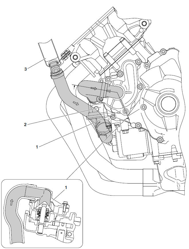
- Water pump
- Thermostat
- Radiator
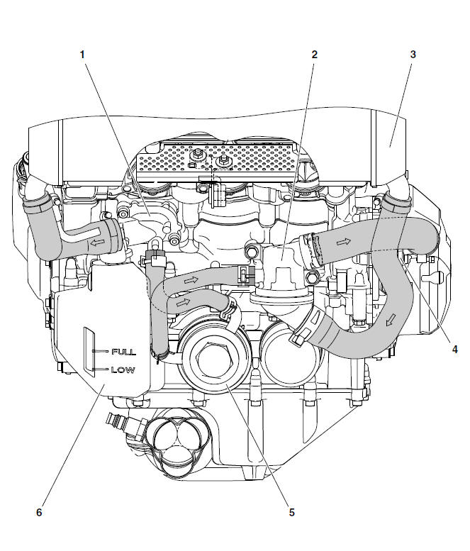
- Water jacket
- Thermostat
- Radiator
- Water pump
- Oil cooler
- Coolant reservoir
Cable routing
Handlebar (top view)
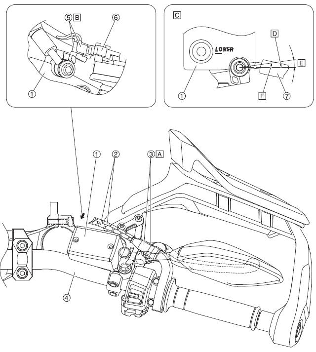
- Front brake master cylinder
- Throttle cable
- Rubber cover
- Handlebar
- Front brake light switch connector
- Front brake light switch
- Front brake hose
- When installing the rubber cover, silicone water or soapy water may be applied to the inside of the rubber cover.
- Connect the front brake light switch connector onto the front brake light switch.
- Detailed drawing of around the front brake master cylinder
- Straight line parallel to the front brake master cylinder reservoir cap
- 3-13º
- Center of the metal fitting for the front brake hose
Handlebar (front view)
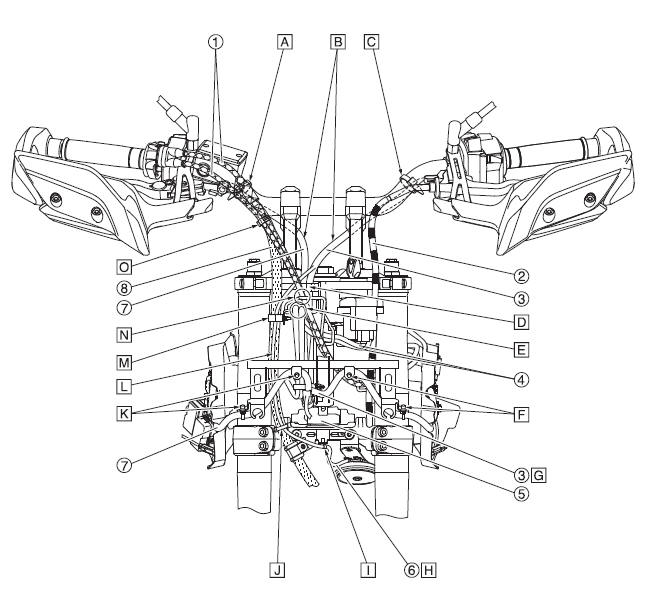
- Throttle cable
- Clutch cable
- Handlebar switch lead (left)
- Main switch lead/Immobilizer lead
- Steering stopper
- Horn lead
- Handlebar switch lead (right)
- Front brake hose
- Fasten the right handlebar switch lead onto the handlebar with the
clamp.
Face the catch of the clamp forward (and upward) with the end pointing downward.
- Pass the right handlebar switch lead and left handlebar switch lead through between the handlebar holders from the rear to the front.
- Fasten the left handlebar switch lead onto the handlebar with the clamp.
Face the catch of the clamp forward (and upward) with the end pointing downward.
- Fasten the left handlebar switch lead and right handlebar switch lead
with the clamp.
Face the opening of the clamp forward.
- Route the main switch lead and immobilizer lead over the guide from the
rear of the vehicle.
Position the main switch lead and immobilizer lead to the right of the throttle cables.
- Insert the clamp of the left handlebar switch lead into the hole in the headlight stay.
- Route the left handlebar switch lead over the wire harness.
- Let the horn lead sag between them.
- Fasten the horn lead to the bracket with the clamp so that the mating
section faces downward.
Route the horn lead on the front side from the hole in the clamp.
- Fasten the horn lead and the protector of the front brake hose with the clamp. Align the position of the clamp with the steering stopper with its opening facing rearward.
- Insert the clamp of the right handlebar switch lead into the hole in the headlight stay.
- Route the horn lead along with the front portion of the brake hoses between the clamps shown.
- Fasten the horn lead and the front brake hose with the clamp and insert
the clamp into the bracket.
Engage the clamp by at least three notches.
Face the opening of the clamp rearward.
- Pass the throttle cables through the guide.
- Fasten the protector of the throttle cable with the clamp.
Face the opening of the clamp rearward.
Radiator (front side view and right side view)
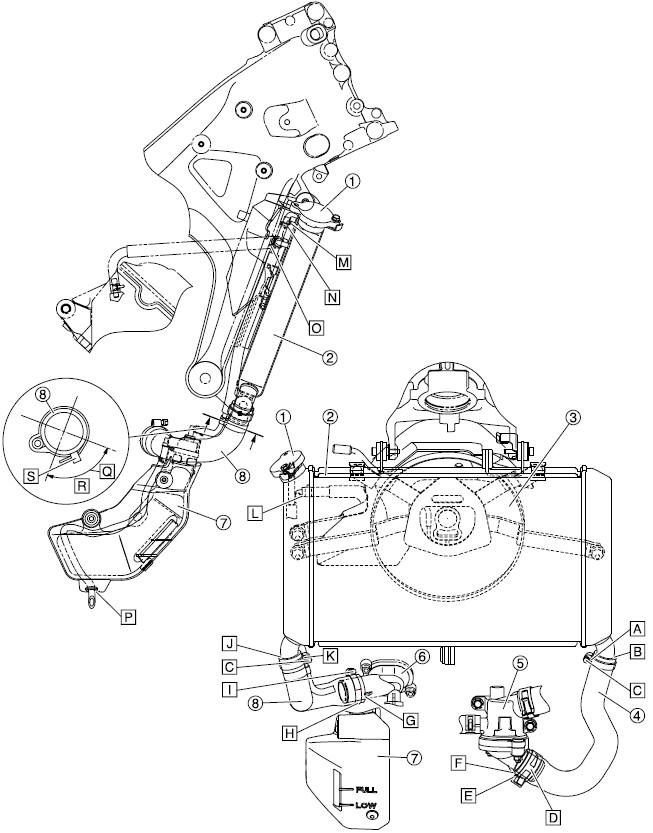
- Radiator cap
- Radiator
- Radiator fan
- Radiator outlet hose
- Thermostat assembly
- Water jacket joint
- Coolant reservoir
- Radiator inlet hose
- Install the radiator outlet hose with its white paint mark facing inward.
- Install the radiator outlet hose up to the base of the bend in the radiator pipe.
- Point the hose clamp installation bolt inward.
- Point the end of the hose clip downward.
- Align the yellow paint mark of the radiator outlet hose with the rib of the thermostat assembly, and then install it.
- Install the radiator outlet hose so that the tip of the hose contacts the rib of the thermostat assembly.
- Install the radiator inlet hose so that the tip of the hose contacts the rib of the water jacket joint.
- Install the radiator inlet hose with its yellow paint mark facing downward.
- Point the hose clamp installation bolt upward.
- Install the radiator inlet hose up to the base of the bend in the radiator pipe.
- Install the radiator inlet hose with its white paint mark facing inward.
- Install the radiator hose up to the base of the bend in the radiator pipe.
- Point the end of the clip outward.
- Install the coolant reservoir hose up to the base of the bend in the radiator pipe.
- Point the end of the clip rearward.
- Install the grommet on the coolant reservoir drain hose to the hole in the coolant reservoir cover.
- Place the lock of the hose clamp within the area shown in the illustration, placing as close to the center as possible.
- R. 90º
- Point the tip of the clamp rearward.
See also:
 Yamaha Tracer MT09TRA - Service manual > Engine oil lubrication chart
Oil strainer Oil pump Relief valve Oil cooler Oil filter cartridge Main gallery Drive axle Main axle Shift fork (upper) Mission shower Crankshaft AC magneto Oil nozzle Balancer shaft Timing chain tensioner Intake camshaft Exhaust camshaft
 Yamaha Tracer MT09TRA - Service manual > Fuel tank (left and bottom view)
Frame Fuel tank Fuel pump Fuel tank drain hose Fuel tank breather hose Clip Fuel hose assembly Insert the fuel tank drain hose up to the section where the fuel tank pipe increases in diameter. Install it so that the white paint mark faces the rearward.

 BMW G310GS
 Honda CBR125RW
 Husqvarna 401 Vitpilen
 KTM 890 Duke R
 Mash Dirt Track 650
 Peugeot Kisbee
 Yamaha Tracer MT-09
 Honda CBR125RW
 Peugeot Kisbee
 Yamaha Tracer MT-09