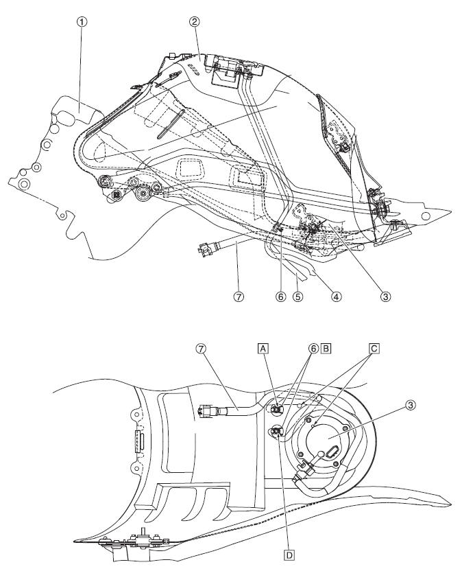
 Yamaha Tracer MT09TRA - Service manual > Fuel tank (left and bottom view)

- Frame
- Fuel tank
- Fuel pump
- Fuel tank drain hose
- Fuel tank breather hose
- Clip
- Fuel hose assembly
- Insert the fuel tank drain hose up to the section where the fuel tank
pipe increases in diameter. Install it so that the white paint mark faces
the rearward.
Position the hose so that its paint mark is visible from the rear of the vehicle. (Within +-45º)
- Install the clip so that the end is on the paint mark. Do not put it on
the clip spool (guard).
Point the end to the rear, and store it inside to the hose.
- Align the fuel pump positioning to the inner panel marking (visual guide during installation).
- Insert the fuel tank breather hose up to the section where the fuel tank
pipe increases in diameter. Install it so that the yellow paint mark faces
the rearward.
Position the hose so that its paint mark is visible from the rear of the vehicle. (Within +-45º)
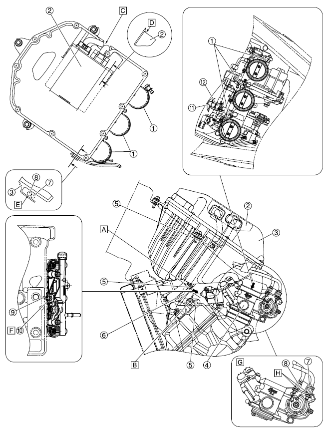
Air filter case and throttle body (top view and left side view)

- Air filter case joint clamp
- ECU (engine control unit)
- Air filter case
- Throttle body
- Clip
- Cylinder head breather hose
- Throttle cable (decelerator cable) (white plating)
- Throttle cable (accelerator cable) (black plating)
- Injector lead
- Injector coupler
- Fuel rail
- Fuel hose (black side)
- Install the breather hose on the yellow paint mark side to the air
filter case, with its yellow paint mark facing toward left side of the
vehicle.
Point the end of the clip toward left.
- Install the breather hose so that the tip touches the pipe of the
cylinder head.
Install the breather hose on the white paint mark side to the engine.
Install the breather hose so that the white paint mark is in the rear of the vehicle and parallel to the cylinder head mating surfaces.
Install the clip so that the end is in the rear of the vehicle and parallel to the cylinder head mating surfaces.
- Install the ECU harness by storing it in the recess in the air filter case.
- Install the ECU so that the hooks on the air filter case go over the ECU edges.
- Store the throttle cables on the protrusion of the air filter case.
- Insert the injector coupler all the way in.
- Instructive drawing for assembling the throttle cables
- Install the throttle cable so that the nut of the throttle cable touches the stay.
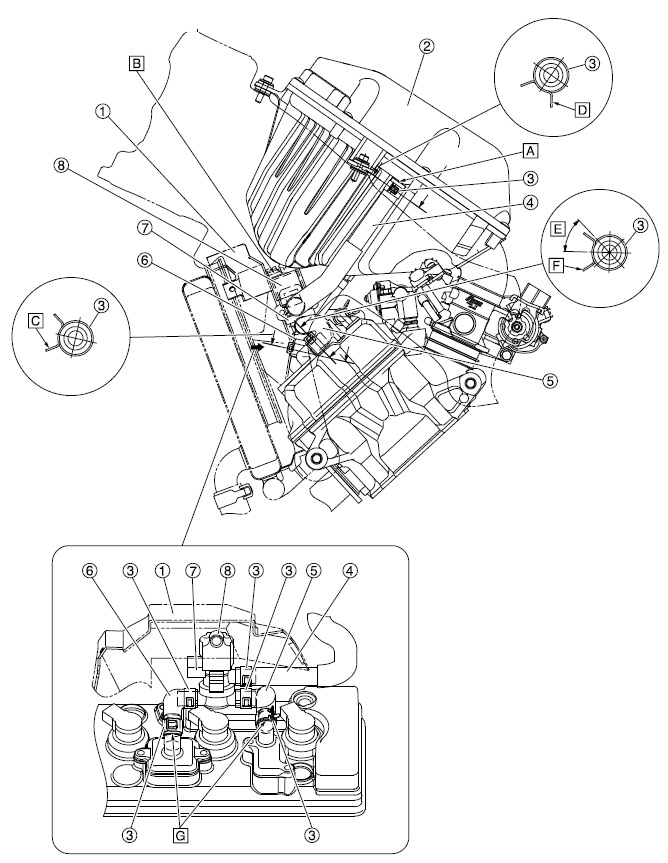
Air cut-off valve (left side view)

- Radiator fan cover
- Air filter case
- Clip
- Air induction system hose (air filter case to air cut-off valve)
- Air induction system hose (air cut-off valve to reed valve cover #1)
- Air induction system hose (air cut-off valve to reed valve cover #2/#3)
- Air cut-off valve
- Air cut-off valve holder
- Install the air induction system hose (air filter case to air cut-off valve) so that the tip of the hose contacts the air filter case.
- Insert the protrusion on the radiator fan cover into the hole in the air cut-off valve holder.
- Point the end of the clip for the air induction system hose (air cut-off valve to reed valve cover #2/#3) forward.
- Point the end of the clip for the air induction system hose (air filter case to air cut-off valve) to the left.
- 45º
- Point the end of the clip for the air induction system hose (air cut-off
valve to reed valve cover #1) diagonally left forward.
G. Install the hose so that the tip of the hose touches the protrusion of the pipe.
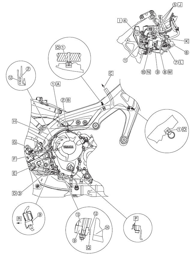
Frame and engine (right side view)

- Clamp
- Rear brake light switch lead
- O2 sensor coupler
- Radiator fan motor coupler
- Handlebar switch coupler (right)
- Inner panel
- Front right turn signal light coupler
- Fuse box 1
- Bracket
- Fuse box 2
- Coupler cover
- O2 sensor lead
- Frame
- Engine
- Insert the clamp into the long hole in the battery box.
- Route the rear brake light switch lead outside the wire harness branch to the O2 sensor lead.
- To the ECU coupler
- Connect the O2 sensor coupler, and then fasten to the bracket. Make sure that the top of the coupler does not protrude. It is okay if the cover is deformed.
- Fasten the O2 sensor lead with the clamp, and then install it on the bracket.
- Route the O2 sensor lead and the rear brake light switch lead through the bracket guide.
- Route the rear brake light switch lead outside brake fluid reservoir hose.
- It does not matter whether the O2 sensor lead or the rear brake light switch lead is on top (bottom) in the area shown in the illustration.
- Connect the radiator fan motor coupler and then position it in front of the connector cover.
- Insert the right handlebar switch coupler into the bracket.
- Insert the clamp of the right handlebar switch lead into the hole in the bracket.
- Insert the front right turn signal light coupler into the inner panel.
- Insert fuse box 1 into the bracket.
- Insert fuse box 2 into the bracket.
- Insert the clamp so that it touches the rim of the frame.
- Fasten the O2 sensor lead with the holder.
- Route O2 sensor lead inside to the protrusion of the bracket.
- Inside vehicle
See also:
 Yamaha Tracer MT09TRA - Service manual > Cooling system diagrams
Water pump Thermostat Radiator Water jacket Thermostat Radiator Water pump Oil cooler Coolant reservoir
 Yamaha Tracer MT09TRA - Service manual > Frame and engine (right side view)
Guide Wire harness Pipe (headlight stay) Clamp Frame Auxiliary DC jack coupler (color: natural) Auxiliary DC jack coupler (color: black) Auxiliary DC jack lead Auxiliary light lead Coupler cover Auxiliary light coupler Throttle cable Wire harness protector Main switch coupler Immobilizer coupler Front wheel sensor coupler Main switch lead Main switch coupler 1 Main switch coupler 2 Sponge Sponge edge Bring the wire harness into contact with the pipe (headlight stay), fasten them with the clamp and then insert the clamp into the hole in the headlight stay.

 BMW G310GS
 Honda CBR125RW
 Husqvarna 401 Vitpilen
 KTM 890 Duke R
 Mash Dirt Track 650
 Peugeot Kisbee
 Yamaha Tracer MT-09
 Honda CBR125RW
 Peugeot Kisbee
 Yamaha Tracer MT-09