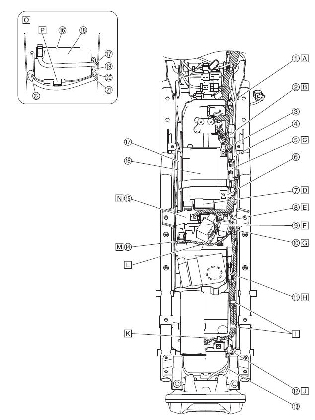
 Yamaha Tracer MT09TRA - Service manual > Frame and engine (right side view)
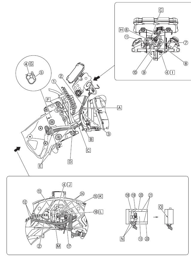
- Guide
- Wire harness
- Pipe (headlight stay)
- Clamp
- Frame
- Auxiliary DC jack coupler (color: natural)
- Auxiliary DC jack coupler (color: black)
- Auxiliary DC jack lead
- Auxiliary light lead
- Coupler cover
- Auxiliary light coupler
- Throttle cable
- Wire harness protector
- Main switch coupler
- Immobilizer coupler
- Front wheel sensor coupler
- Main switch lead
- Main switch coupler 1
- Main switch coupler 2
- Sponge
- Sponge edge
- Bring the wire harness into contact with the pipe (headlight stay),
fasten them with the clamp and then insert the clamp into the hole in the
headlight stay.
Make sure that the end of the clamp faces forward when inserting it into the hole in the headlight stay. It is not necessary to insert the end of the clamp further into the hole opposite to the hole in which it has been inserted.
- Connect the coupler to the headlight unit.
- Insert the clamp of the wire harness into the hole in the headlight stay.
- Fasten the main switch lead, immobilizer lead and handlebar switch leads
with the clamp.
Make sure that the main switch lead and immobilizer lead are positioned backward and the handlebar switch leads positioned forward. Then, insert the clamp into the hole in the headlight stay.
Align the clamp with the tapes (red to the left and blue to the right) on the handlebar switch lead and face the end of the clamp forward.
- Make sure that there is no slack in the main switch lead and immobilizer lead between the clamps shown.
- Make sure that the main switch lead, immobilizer lead and handlebar switch leads are not twisted between the clamps shown.
- Fasten the wire harness, main switch lead, and immobilizer lead with the
clamp.
The wire harness, main switch lead, and immobilizer lead should be fastened with the clamp at the white tape.
Point the tip of the clamp outward, and then cut it.
- Connect the auxiliary DC jack to the auxiliary DC jack coupler (color: natural) on the wire harness.
- Fasten the auxiliary light lead and auxiliary DC jack lead with the clamp and then insert the clamp into the hole in the headlight stay.
- Fasten the main switch lead to the coupler cover with the clamp.
- The positions for the leads on the immobilizer unit side do not matter regarding the main switch lead.
- Route the front wheel sensor lead rear side of the vehicle respect to the main switch lead.
- Install the clamp to the hole in the bottom of the coupler cover.
- Make sure that the main switch coupler does not protrude from the sponge edge.
- Align the wire harness protector with the edge of the Velcro tape and wrap it. However, the tape surface may protrude somewhat.
Frame and engine (left side view)
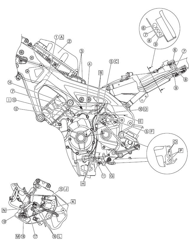
- Air induction system hose (air filter case to air cut-off valve)
- Air filter case
- Throttle cables
- Stator coil assembly lead
- Clamp
- Positive battery lead
- Starter motor lead
- Stator coil lead
- Wire harness (to rectifier/regulator)
- Gear position switch lead
- Sidestand switch lead
- Oil level switch lead
- Boots
- Clutch cable
- Intake air temperature sensor coupler
- Handlebar switch coupler (left)
- Bracket
- Front left turn signal light coupler
- Inner panel
- Route the air induction system hose (air filter case to air cut-off valve) inside the throttle cable.
- Route the fuel tank drain hose/fuel tank breather hose outside to the
wire harnesses.
Route them inside to the brake hose.
- Fasten the sidestand switch lead, stator coil assembly lead, starter
motor lead and oil level switch lead with the clamp. The order of the leads
does not matter. Align the clamp with the tape on the starter motor lead. Do
not cut off the clamp end and point it forward.
Pull the oil level switch lead when fastening.
- Route the gear position switch lead inside to the shift arm.
- Hose bending edge
- Align the sidestand switch lead, oil level switch lead, fuel tank drain hose, and fuel tank breather hose with the bending edge of the hose, and then install them. Face the clamp opening to the rearward.
- 30-50 mm (1.18-1.97 in)
- Point the tips of fuel tank drain hose and fuel tank breather hose as shown in the illustration.
- Place the stator coil assembly lead so that bare copper wires do not protrude from the boots.
- Install the intake air temperature sensor coupler on the rib of the bracket.
- Insert the clamp of the wire harness into the hole in the bracket.
- Insert the left handlebar switch coupler into the bracket.
- Insert the front left turn signal light coupler into the inner panel.
- Insert the clamp of the left handlebar switch lead into the hole in the bracket.
- It does not matter whether the oil level switch lead or the sidestand switch lead is on top.
- It does not matter whether the fuel tank drain hose or the fuel tank breather hose is on top but make sure that these hoses are not twisted each other.
Frame (top view)
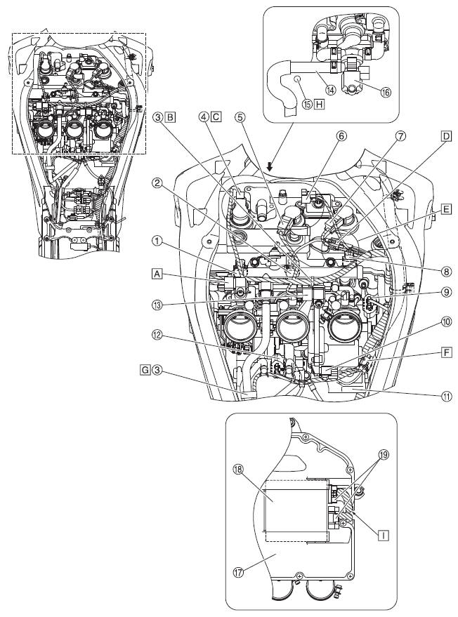
- Injector #1 coupler
- Injector #2 coupler
- Clamp
- Ignition coil #1 coupler
- Ignition coil #2 coupler
- Air cut-off valve coupler
- Ignition coil #3 coupler
- Injector #3 coupler
- Throttle position sensor coupler
- Throttle servo motor coupler
- Cross tube
- Accelerator position sensor coupler
- Intake air pressure sensor coupler
- Air induction system hose (air filter case to air cut-off valve)
- Clutch cable
- Air cut-off valve
- Air filter case
- ECU (engine control unit)
- ECU (engine control unit) coupler
- Fold back the intake air pressure sensor lead by the coupler, and then fasten it with tape.
- Insert the clamp into the fuel rail hole.
- Fold back the injector lead #1 by the coupler, and then fasten it with tape.
- Connect the sub-lead to the injector coupler #2. Fasten the injector coupler on the wire harness side with tape.
- For the air cut-off valve lead, ignition coil lead #3, and fuel injector lead #3, it does not matter which is routed above the others.
- Route the coolant temperature sensor sublead between the cross tube and the wire harness.
- Fasten the coolant temperature sensor coupler on the wire harness side with tape. Fasten the fuel hose at the mark and the wire harness at the positioning tape with the clamp. The opening of the clamp can face either way.
- Route the clutch cable above to the air induction system hose (air filter case to air cut-off valve).
- Route the ECU lead for the front of the vehicle through the rib of the air filter case.
Frame (top view)
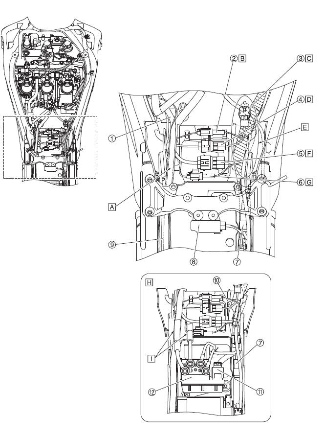
- Stator coil assembly lead
- Oil level switch coupler
- Rear brake light switch coupler
- Sidestand switch coupler
- Gear position switch coupler 1
- Gear position switch coupler 2
- Negative battery lead coupler
- Lean angle sensor
- Starter motor lead
- Negative battery lead 2 coupler
- ABS ECU coupler
- Hydraulic unit
- Leads on the front of the battery box are, from the top of the vehicle, in the following order: starter motor lead, stator coil assembly lead. The orders for other leads do not matter.
- Fasten the wire harness side of the oil level switch coupler to the battery box.
- Fasten the rear brake light switch coupler of the wire harness with tape.
- Fasten the sidestand switch coupler of the wire harness to the battery box.
- Route the negative battery lead inside to the branch of the O2 sensor lead and the rear brake light switch lead, and through between the wire harness and the frame. For rear side of the vehicle, route it above the wire harness.
- Fasten the wire harness side of gear position switch coupler 1 to the battery box.
- Fasten the wire harness side of gear position switch coupler 2 to the battery box.
- Details around the hydraulic unit
- Route the brake hose above all the other leads.
Frame (top view)
- Rear wheel sensor coupler
- Negative battery lead coupler
- Positive battery terminal
- Negative battery lead
- Radiator fan motor relay
- Negative battery terminal
- Fuse box
- Relay unit
- Turn signal/hazard relay
- Clamp
- Rear turn signal light coupler (left/right)
- Tail/brake light coupler
- Tail/brake light lead
- Yamaha diagnostic tool coupler
- Starter relay
- Battery
- Positive battery lead
- Battery box
- Starter motor lead
- Stator coil lead
- Wire harness (to rectifier/regulator)
- Wire harness
- Position the rear wheel sensor coupler under the negative battery lead.
- Position the negative battery lead coupler under the negative battery lead.
- Install the rubber bracket of the radiator fan motor relay in the battery box. Make sure to route the lead under the relay.
- Fasten the fuse box onto the battery box.
- Install the rubber bracket of the relay unit in the battery box.
- Install the rubber bracket of the turn signal/ hazard relay in the battery box.
- Install the clamp into the hole in the battery box.
- Connect each rear turn signal coupler to the coupler with the same color. After connecting the license plate light coupler, store the turn signal light coupler (left/right) furthest to the bottom of the vehicle. After connecting the other couplers, store them below the tail/brake light lead.
- Route the tail/brake light lead, turn signal light lead, and license plate light lead through the cutout of the battery box. The order of the leads does not matter.
- Fasten the wire harness side of the tail/brake light coupler to the battery box.
- Route the turn signal light lead, and license plate light lead through the cutout of the battery box. The order of the leads does not matter.
- Route the Yamaha diagnostic tool coupler lead at the bottom of the battery box.
- Insert the Yamaha diagnostic tool coupler to the battery box.
- Install the rubber bracket of the starter relay in the battery box.
- Instructional drawing for routes in the front of the battery
- Fasten the crankshaft position sensor coupler of the wire harness with tape.
See also:
 Yamaha Tracer MT09TRA - Service manual > Fuel tank (left and bottom view)
Frame Fuel tank Fuel pump Fuel tank drain hose Fuel tank breather hose Clip Fuel hose assembly Insert the fuel tank drain hose up to the section where the fuel tank pipe increases in diameter. Install it so that the white paint mark faces the rearward.
 Yamaha Tracer MT09TRA - Service manual > Front brake (right side view and left side view)
Front brake hose Front wheel sensor lead Clamp Front wheel sensor protector Brake caliper (right) Front fender Brake caliper (left) Front wheel sensor Front wheel sensor housing Front wheel sensor lead holder Position the clamp by aligning it with the top edge of the protector of the front wheel sensor lead when the protector is placed at the bottom. Install the brake pipe so that it contacts the projection on the brake caliper. Install the clamp so that the bottom side of the clamp is 10-30 mm (0.39-1.18 in) from the end of the front brake pipe.

 BMW G310GS
 Honda CBR125RW
 Husqvarna 401 Vitpilen
 KTM 890 Duke R
 Mash Dirt Track 650
 Peugeot Kisbee
 Yamaha Tracer MT-09
 Honda CBR125RW
 Peugeot Kisbee
 Yamaha Tracer MT-09