 Yamaha Tracer MT09TRA - Service manual > Front fork


Removing the front fork legs
The following procedure applies to both of the front fork legs.
TIP
Each front fork leg is equipped with a spring preload adjusting bolt, the right fork leg is equipped with a rebound damping force adjusting screw.
Pay attention not to mistake the right and left.
1. Stand the vehicle on a level surface.
WARNING
Securely support the vehicle so that there is no danger of it falling over.
TIP
Place the vehicle on a suitable stand so that the front wheel is elevated.
2. Remove:
- Front brake caliper
Refer to "FRONT BRAKE"
- Front wheel
Refer to "FRONT WHEEL"
3. Loosen:
- Upper bracket pinch bolt "1"
- Cap bolt "2"
- Lower bracket pinch bolts "3"
WARNING
Before loosening the upper and lower bracket pinch bolts, support the front fork leg.

4. Remove:
- Front fork leg
Disassembling the front fork legs
The following procedure applies to both of the front fork legs.
1. Remove:
- Cap bolt "1" (from the damper rod assembly)
- Washer "2"
- Spacer "3"
- Locknut "4"
a. Press down on the spacer with the fork spring compressor "5".
b. Install the rod holder "6" between the locknut "4" and the spacer "3".
 Fork spring compressor
90890-01441
Fork spring compressor YM-01441
Rod holder 90890-01434
Damper rod holder double ended YM-01434
TIP
Use the side of the rod holder that is marked "B".

c. Hold the cap bolt and loosen the locknut.
d. Remove the cap bolt and washer.
e. Remove the rod holder and fork spring compressor.
f. Remove the spacer and locknut.
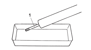
2. Drain:
- Fork oil
TIP
Stroke the damper rod assembly "1" several times while draining the fork oil.
3. Remove:
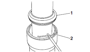
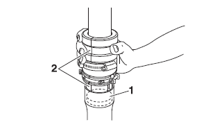
- Dust seal "1"
- Oil seal clip "2" (with a flat-head screwdriver)
NOTICE
Do not scratch the outer tube.
4. Remove:
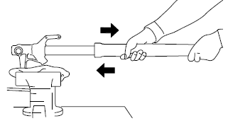
- Outer tube
a. Hold the front fork leg horizontally.
b. Securely clamp the brake caliper bracket in a vise with soft jaws.
c. Separate the outer tube from the inner tube by pulling the outer tube forcefully but carefully.
NOTICE
Excessive force will damage the bushings.
Damaged bushings must be replaced.
5. Remove:
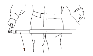
- Damper rod assembly bolt
- Damper rod assembly
NOTICE
For the damper rod assembly, the right side is used for the rebound operation. Pay attention not to mistake the right and left.
TIP
While holding the damper rod with the damper rod holder "1", loosen the damper rod assembly bolt.
 Damper rod holder
90890-01582
Damper rod holder YM-01582
Checking the front fork legs
The following procedure applies to both of the front fork legs.
1. Check:
- Inner tube "1"
- Outer tube "2"
Bends/damage/scratches → Replace.
WARNING
Do not attempt to straighten a bent inner tube as this may dangerously weaken it.

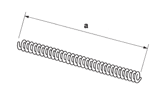
2. Measure:
- Spring free length "a"
Out of specification → Replace.
 Fork spring free length
305.3 mm (12.02 in)
Limit 299.3 mm (11.78 in)
3. Check:
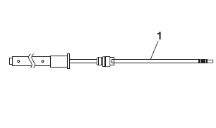
- Damper rod "1"
Damage/wear → Replace.
Obstruction → Blow out all of the oil passages with compressed air.
NOTICE
- The front fork leg has a very sophisticated internal construction, which are particularly sensitive to foreign material.
- When disassembling and assembling the front fork leg, do not allow any foreign material to enter the front fork.
Assembling the front fork legs
The following procedure applies to both of the front fork legs.
WARNING
- Note that the amount of the fork oil is different in the left and right front fork legs. Make sure to fill each of the left and right front fork legs with the specified amount of the fork oil.
- If both front fork legs are not filled with the specified amount of the fork oil, it may cause poor handling and a loss of stability.
TIP
When assembling the front fork leg, be sure to replace the following parts:
- Inner tube bushing
- Outer tube bushing
- Oil seal
- Oil seal clip
- Dust seal
- Copper washer
- O-ring
Before assembling the front fork leg, make sure all of the components are clean.
1. Install:
- Damper rod assembly "1"
NOTICE
Allow the damper rod assembly to slide slowly down the inner tube "2" until it protrudes from the bottom of the inner tube. Be careful not to damage the inner tube.
TIP
The left side damper rod assembly has the two holes of oil path, unlike the right side.

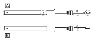
A. Left side
B. Right side
2. Tighten:
- Damper rod assembly bolt (along with the copper washer
 )
)
 Front fork damper rod
assembly bolt 23 Nm (2.3 m*kgf, 17 ft*lbf) LOCTITE
TIP
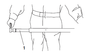
While holding the damper rod assembly with the damper rod holder "1", tighten the damper rod assembly bolt.
 Damper rod holder
90890-01582
Damper rod holder YM-01582
3. Lubricate:
- Inner tube's outer surface
 Recommended oil
Suspension oil 01 or equivalent
4. Install:
- Dust seal "1"

- Oil seal clip "2"

- Oil seal "3"

- Washer "4"
- Outer tube bushing "5"

- Inner tube bushing "6"

NOTICE
Make sure the numbered side of the oil seal faces bottom side.
TIP
- Before installing the oil seal, lubricate its lips with lithium-soap-based grease.
- Lubricate the outer surface of the inner tube with fork oil.
- Before installing the oil seal, cover the top of the front fork leg with a plastic bag to protect the oil seal during installation.

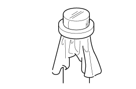
5. Install:
- Outer tube (to the inner tube)
6. Install:
- Outer tube bushing "1"
- Washer "2" (with the fork seal driver "3")
 Fork seal driver
90890-01442 Adjustable fork seal driver (36-46 mm) YM-01442

7. Install:
- Oil seal "1" (with the fork seal driver "2")
 Fork seal driver
90890-01442 Adjustable fork seal driver (36-46 mm) YM-01442
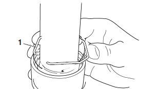
8. Install:
- Oil seal clip "1"
TIP
Adjust the oil seal clip so that it fits into the outer tube's groove.
9. Install:
- Dust seal "1" (with the fork seal driver "2")
 Fork seal driver
90890-01442
Adjustable fork seal driver (36-46 mm) YM-01442

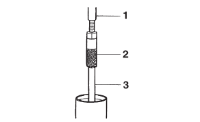
10.Install:
- Rod puller "1"
- Rod puller attachment (M10 long) "2" (onto the damper rod "3")
 Rod puller 90890-01437
Universal damping rod bleeding tool set YM-A8703
Rod puller attachment (M10 long) 90890-01578
Universal damping rod bleeding tool set YM-A8703
11.Fill:
- Front fork leg (with the specified amount of the recommended fork oil)
 Recommended oil
Suspension oil 01 or equivalent Quantity (left)
444.0 cm³ (15.01 US oz, 15.66 Imp.oz)
Quantity (right) 431.0 cm³ (14.57 US oz, 15.20 Imp.oz)
NOTICE
- Be sure to use the recommended fork oil.
Other oils may have an adverse effect on front fork performance.
- When disassembling and assembling the front fork leg, do not allow any foreign material to enter the front fork.
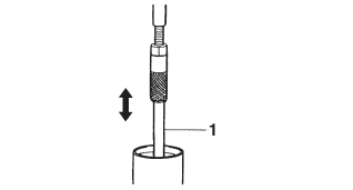
12.After filling the front fork leg, slowly stroke the damper rod "1" up and down (at least ten times) to distribute the fork oil.
TIP
Be sure to stroke the damper rod slowly because the fork oil may spurt out.
TIP
Be sure to bleed the front fork leg of any residual air.
14.Measure:
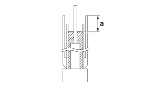
- Front fork leg oil level "a" (from the top of the outer tube, with the outer tube fully compressed and without the fork spring)
Out of specification → Correct.
 Level (left) 174 mm
(6.9 in)
Level (right) 175 mm (6.9 in)
15.Install:
- Fork spring (left side) "1"
- Spacer (left side) "2"
- Locknut (left side) "3"
- Washer (left side) "4"
- Cap bolt (left side) "5" (along with the O-ring
 )
)

a. Remove the rod puller and rod puller attachment.
b. Install the fork spring.
TIP
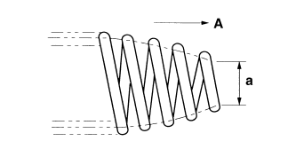
Install the fork spring with the smaller diameter "a" facing up "A".
c. Install the locknut all the way onto the damper rod assembly.
d. Install the rod puller and rod puller attachment.
e. Install the spacer.
f. Install the fork spring compressor.
g. Press down on the spacer with the fork spring compressor "1".
h. Pull up the rod puller and install the rod holder "2" between the locknut "3" and the spacer "4".
 Rod puller 90890-01437
Universal damping rod bleeding tool set YM-A8703
Rod puller attachment (M10 long) 90890-01578
Universal damping rod bleeding tool set YM-A8703
Fork spring compressor 90890-01441
Fork spring compressor YM-01441
Rod holder 90890-01434
Damper rod holder double ended YM-01434
TIP
Use the side of the rod holder that is marked "B".

i. Remove the rod puller and rod puller attach- ment.
j. Install the washer and cap bolt, and then finger tighten the cap bolt.
WARNING
Always use a new cap bolt O-ring.
k. Hold the cap bolt "5" and tighten the locknut "3" to specification.
 Front fork cap bolt
locknut 15 Nm (1.5 m*kgf, 11 ft*lbf)

l. Remove the rod holder and fork spring compressor.
16.Install:
- Fork spring (right side) "1"
- Spacer (right side) "2"
- Locknut (right side) "3"
- Damper adjusting rod "4"
- Washer (right side) "5"
- Cap bolt (right side) "6" (along with the O-ring
 )
)

a. Remove the rod puller and rod puller attachment.
b. Install the fork spring.
TIP
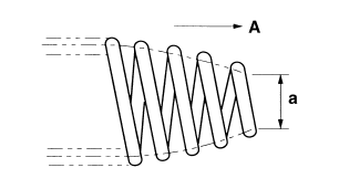
Install the fork spring with the smaller diameter "a" facing up "A".
c. Install the locknut all the way onto the damper rod assembly.
d. Install the rod puller and rod puller attachment.
e. Install the spacer.
f. Install the fork spring compressor.
g. Press down on the spacer with the fork spring compressor "1".
h. Pull up the rod puller and install the rod holder "2" between the locknut "3" and the spacer "4".
 Rod puller 90890-01437
Universal damping rod bleeding tool set YM-A8703
Rod puller attachment (M10 long) 90890-01578
Universal damping rod bleeding tool set YM-A8703
Fork spring compressor 90890-01441
Fork spring compressor YM-01441
Rod holder 90890-01434
Damper rod holder double ended YM-01434
TIP
Use the side of the rod holder that is marked "B".

i. Remove the rod puller and rod puller attachment.
j. Position the locknut "3" as specified "b".
 Distance "b" 12 mm (0.47
in)

k. Set the cap bolt distance "c" to specification
 Distance "c" 13 mm
(0.51 in)
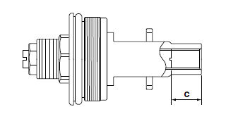
l. Install the damper adjusting rod, washer and cap bolt, and then finger tighten the cap bolt
WARNING
Always use a new cap bolt O-ring.
m. Hold the cap bolt "5" and tighten the locknut "3" to specification.
 Front fork cap bolt
locknut 15 Nm (1.5 m*kgf, 11 ft*lbf)

n. Remove the rod holder and fork spring compressor.
17.Install:
- Cap bolt (to the outer tube)
TIP
- Temporarily tighten the cap bolt.
- When to tighten the cap bolt to the specified torque is after installing the front fork leg to the vehicle and tightening the lower bracket pinch bolts.
Installing the front fork legs
The following procedure applies to both of the front fork legs.
1. Install:
- Front fork leg
Temporarily tighten the upper and lower bracket pinch bolts.
TIP
Make sure the outer tube is flush with the top of the upper bracket.
2. Tighten:
- Lower bracket pinch bolts "1"
 Lower bracket pinch bolt
23 Nm (2.3 m*kgf, 17 ft*lbf)
- Cap bolt "2"
 Front fork cap bolt 23
Nm (2.3 m*kgf, 17 ft*lbf)
- Upper bracket pinch bolt "3"
 Upper bracket pinch bolt
26 Nm (2.6 m*kgf, 19 ft*lbf)
WARNING
Make sure the brake hoses are routed properly.

See also:
 Yamaha Tracer MT09TRA - Service manual > Handlebar
Adjusting the handlebar position

 BMW G310GS
 Honda CBR125RW
 Husqvarna 401 Vitpilen
 KTM 890 Duke R
 Mash Dirt Track 650
 Peugeot Kisbee
 Yamaha Tracer MT-09
 Honda CBR125RW
 Peugeot Kisbee
 Yamaha Tracer MT-09