 Yamaha Tracer MT09TRA - Service manual > Handlebar


Adjusting the handlebar position
1. Check:
- Handlebar position
TIP
The handlebar position can be adjusted in two positions to suit the rider's preference.

2. Remove:
- Fuel tank front cover/Front side panel/Front side cowling Refer to "GENERAL CHASSIS (2)"
3. Adjust:
- Handlebar position
a. Remove the upper handlebar holders "1" and handlebar "2".

b. Loosen the lower handlebar holder nuts.
c. Adjust the handlebar position by rotating both of the lower handlebar holders "3" in 180º.

d. Install the handlebar "2" and upper handlebar holders "1".
 Upper handlebar holder
bolt 22 Nm (2.2 m*kgf, 16 ft*lbf)
NOTICE
- First, tighten the bolts on the front side of the upper handlebar holder, and then on the rear side.
- Turn the handlebar all the way to the left and right. If there is any contact with the fuel tank, adjust the handlebar position.
TIP
Align the punch mark "a" on the handlebar with the left side upper surface of the left lower handlebar holder "4".

e. Tighten the lower handlebar holder nuts.
 Lower handlebar holder
nut 40 Nm (4.0 m*kgf, 29 ft*lbf)
4. Install:
Front side cowling/Front side panel/Fuel tank front cover Refer to "GENERAL CHASSIS (2)"
Removing the handlebar
1. Stand the vehicle on a level surface.
WARNING
Securely support the vehicle so that there is no danger of it falling over.
2. Remove:
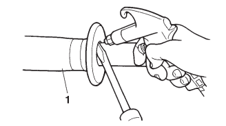
- Handlebar grip "1"
TIP
Blow compressed air between the left handlebar and the handlebar grip, and gradually push the grip off the handlebar.

3. Remove:
- Throttle cable housings "1"
- Throttle grip "2"
TIP
While removing the throttle cable housing, pull back the rubber cover "3".

Checking the handlebar
1. Check:
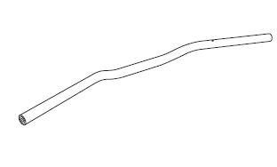
- Handlebar
Bends/cracks/damage → Replace.
WARNING
Do not attempt to straighten a bent handlebar as this may dangerously weaken it.

Installing the handlebar
1. Stand the vehicle on a level surface.
WARNING
Securely support the vehicle so that there is no danger of it falling over.
2. Install:
- Lower handlebar holders (temporarily)
- Handlebar "1"
- Upper handlebar holders "2"
 Upper handlebar holder
bolt 22 Nm (2.2 m*kgf, 16 ft*lbf)
NOTICE
- First, tighten the bolts on the front side of the upper handlebar holder, and then on the rear side.
- Turn the handlebar all the way to the left and right. If there is any contact with the fuel tank, adjust the handlebar position.
TIP
Align the punch mark "a" on the handlebar with the left side upper surface of the left lower handlebar holder "3".

3. Tighten:
- Lower handlebar holder nuts
 Lower handlebar holder
nut 40 Nm (4.0 m*kgf, 29 ft*lbf)
4. Install:
- Throttle grip
- Throttle cables
- Throttle cable housings "2"
- Grip end
 Throttle cable housing
bolt 3.8 Nm (0.38 m*kgf, 2.8 ft*lbf)
Grip end 26 Nm (2.6 m*kgf, 19 ft*lbf)
TIP
Align the projection "a" on the throttle cable housing with the hole "b" in the handlebar.

5. Install:
- Handlebar switch screw (right)
 Handlebar switch screw
3.5 Nm (0.35 m*kgf, 2.5 ft*lbf)
TIP
Align the projection "a" on the right handlebar switch with the hole "b" in the handlebar.

6. Install:
- Front brake master cylinder assembly
Refer to "INSTALLING THE FRONT BRAKE MASTER CYLINDER"
7. Install:
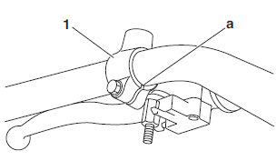
- Clutch lever holder "1"
- Clutch cable
 Clutch lever holder
pinch bolt 11 Nm (1.1 m*kgf, 8.0 ft*lbf)
TIP
Align the center of slit on the clutch lever holder with the punch mark "a" on the handlebar.

8. Install:
- Handlebar switch screw (left)
 Handlebar switch screw
3.5 Nm (0.35 m*kgf, 2.5 ft*lbf)
TIP
Align the projection "a" on the left handlebar switch with the hole "b" in the handlebar.

9. Install:
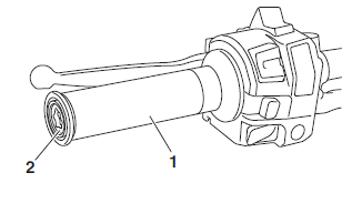
- Handlebar grip "1"
- Grip end "2"
 Grip end 26 Nm (2.6
m*kgf, 19 ft*lbf)
a. Apply a thin coat of rubber adhesive onto the end of the left handlebar.
b. Side the handlebar grip over the end of the left handlebar.
c. Wipe off any excess rubber adhesive with a clean rag.
WARNING
Do not touch the handlebar grip until the rubber adhesive has fully dried.

10.Adjust:
- Throttle grip free play
Refer to "CHECKING THE THROTTLE GRIP"
 Throttle grip free play
3.0-5.0 mm (0.12-0.20 in)
11.Adjust:
- Clutch lever free play
Refer to "ADJUSTING THE CLUTCH LEVER FREE PLAY"
 Clutch lever free play
10.0-15.0 mm (0.39-0.59 in)
Installing the rearview mirrors and handguards
1. Install:
- Handguard (left) "1"
- Rearview mirror (left) "2"
a. Install the handguard and rearview mirror.
TIP
Temporarily tighten the handguard bracket bolts "3", rearview mirror locknut "4", handguard bolt "5" and handguard bracket nut "6".

b. Tighten the handguard bracket bolts "3" to specification.
 Handguard bracket bolt 7
Nm (0.7 m*kgf, 5.1 ft*lbf)
c. Tighten the rearview mirror locknut "4" to specification.
 Rearview mirror locknut
17 Nm (1.7 m*kgf, 12 ft*lbf)
d. Tighten the handguard bolt "5" to specification.
 Handguard bolt 17 Nm
(1.7 m*kgf, 12 ft*lbf)
e. Tighten the handguard bracket nut "6" to specification.
 Handguard bracket nut
(left) 7 Nm (0.7 m*kgf, 5.1 ft*lbf)
2. Install:
- Handguard (right) "1"
- Rearview mirror (right) "2"
a. Install the handguard and rearview mirror.
TIP
Temporarily tighten the handguard bracket bolts "3", rearview mirror locknut "4", handguard bolt "5" and handguard bracket nut "6".

b. Tighten the handguard bracket bolts "3" to specification.
 Handguard bracket bolt 7
Nm (0.7 m*kgf, 5.1 ft*lbf)
c. Tighten the rearview mirror locknut "4" to specification.
 Rearview mirror locknut
17 Nm (1.7 m*kgf, 12 ft*lbf)
d. Tighten the handguard bolt "5" to specification.
 Handguard bolt 17 Nm (1.7
m*kgf, 12 ft*lbf)
e. Tighten the handguard bracket nut "6" to specification.
 Handguard bracket nut
(right) 6 Nm (0.6 m*kgf, 4.3 ft*lbf)
See also:
 Yamaha Tracer MT09TRA - Service manual > Hydraulic unit operation tests
The reaction-force pulsating action generated in the brake lever and brake pedal when the ABS is activated can be tested when the vehicle is stopped. The hydraulic unit operation can be tested using the following two methods. Brake line routing confirmation: this test checks the function of the ABS after the system was disassembled, adjusted, or serviced. ABS reaction-force confirmation: this test generates the same reaction-force pulsating action that is generated in the brake lever and brake pedal when the ABS is activated.

 BMW G310GS
 Honda CBR125RW
 Husqvarna 401 Vitpilen
 KTM 890 Duke R
 Mash Dirt Track 650
 Peugeot Kisbee
 Yamaha Tracer MT-09
 Honda CBR125RW
 Peugeot Kisbee
 Yamaha Tracer MT-09