 Yamaha Tracer MT09TRA - Service manual > Hydraulic unit operation tests
The reaction-force pulsating action generated in the brake lever and brake pedal when the ABS is activated can be tested when the vehicle is stopped.
The hydraulic unit operation can be tested using the following two methods.
- Brake line routing confirmation: this test checks the function of the ABS after the system was disassembled, adjusted, or serviced.
- ABS reaction-force confirmation: this test generates the same reaction-force pulsating action that is generated in the brake lever and brake pedal when the ABS is activated.
Brake line routing confirmation
WARNING
Securely support the vehicle so that there is no danger of it falling over.
TIP
- For the brake line routing confirmation, use the diagnosis mode of the Yamaha diagnostic tool.
- Before performing the brake line routing confirmation, make sure that no malfunctions have been detected in the ABS ECU and that the wheels are not rotating.
1. Place the vehicle on the centerstand.
2. Turn the main switch to "OFF".
3. Remove:
- Passenger seat/Rider seat
4. Check:
- Battery voltage
Lower than 12.8 V → Charge or replace the battery.
 Battery voltage Higher
than 12.8 V
TIP
If the battery voltage is lower than 12.8 V, charge the battery, and then perform brake line routing confirmation.

5. Removing the protective cap "1", and then connect the Yamaha diagnostic tool to the ABS test coupler (4P).
 Yamaha diagnostic tool
90890-03231

6. Start the Yamaha diagnostic tool and display the diagnosis mode screen.
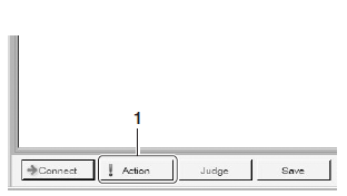
7. Select code No. 2, "Brake line routing confirmation".
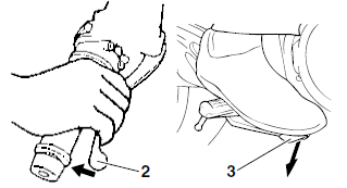
8. Click "Action" "1", and then operate the brake lever "2" and brake pedal "3" simultaneously.
TIP
- The hydraulic unit operates 1 second after the brake lever and brake pedal are operated simultaneously and continues for approximately 5 seconds.
- The operation of the hydraulic unit can be confirmed using the
indicator.
On: The hydraulic unit is operating.
Flashing: The conditions for operating the hydraulic unit have not been met.
Off: The brake lever and brake pedal are not being operated.
9. Check:
- Hydraulic unit operation
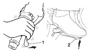
Click "Action", a single pulse will be generated in the brake lever "1", brake pedal "2", and again in the brake lever "1", in this order.
TIP
"ON" and "OFF" on the tool screen indicate when the brakes are being applied and released respectively.
NOTICE
- Check that the pulse is felt in the brake lever, brake pedal, and again in the brake lever, in this order.
- If the pulse is felt in the brake pedal before it is felt in the brake lever, check that the brake hoses and brake pipes are connected correctly to the hydraulic unit assembly.
- If the pulse is hardly felt in either the brake lever or brake pedal, check that the brake hoses and brake pipes are connected correctlycorrectly to the hydraulic unit assembly.
10.If the operation of the hydraulic unit is normal, delete all of the fault codes.
ABS reaction-force confirmation
WARNING
Securely support the vehicle so that there is no danger of it falling over.
TIP
- For the ABS reaction-force confirmation, use the diagnosis mode of the Yamaha diagnostic tool. For more information, refer to the operation manual of the Yamaha diagnostic tool.
- Before performing the ABS reaction-force confirmation, make sure that no malfunctions have been detected in the ABS ECU and that the wheels are not rotating.
1. Place the vehicle on the centerstand.
2. Turn the main switch to "OFF".
3. Remove:
- Passenger seat/Rider seat
4. Check:
- Battery voltage
Lower than 12.8 V → Charge or replace the battery.
 Battery voltage Higher
than 12.8 V
TIP
If the battery voltage is lower than 12.8 V, charge the battery, and then perform ABS reactionforce confirmation.

5. Removing the protective cap "1", and then connect the Yamaha diagnostic tool to the ABS test coupler (4P).
 Yamaha diagnostic tool
90890-03231

6. Start the Yamaha diagnostic tool and display the diagnosis mode screen.
7. Select code No. 1, "ABS reaction-force confirmation".
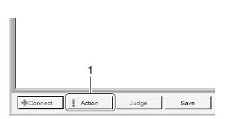
8. Click "Action" "1", and then operate the brake lever "2" and brake pedal "3" simultaneously.
TIP
- The hydraulic unit operates 1 second after the brake lever and brake pedal are operated simultaneously and continues for approximately 5 seconds.
- The operation of the hydraulic unit can be confirmed using the
indicator.
On: The hydraulic unit is operating.
Flashing: The conditions for operating the hydraulic unit have not been met.
Off: The brake lever and brake pedal are not being operated.
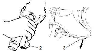
9. A reaction-force pulsating action is generated in the brake lever "1" and continues for a few seconds.
TIP
- The reaction-force pulsating action consists of quick pulses.
- Be sure to continue operating the brake lever and brake pedal even after the pulsating action has stopped.
- "ON" and "OFF" on the tool screen indicate when the brakes are being applied and released respectively.
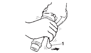
10.After the pulsating action has stopped in the brake lever, it is generated in the brake pedal "1" and continues for a few seconds.
TIP
- The reaction-force pulsating action consists of quick pulses.
- Be sure to continue operating the brake lever and brake pedal even after the pulsating action has stopped.
- "ON" and "OFF" on the tool screen indicate when the brakes are being applied and released respectively.

11.After the pulsating action has stopped in the brake pedal, it is generated in the brake lever and continues for a few seconds.
TIP
- The reaction-force pulsating action consists of quick pulses.
- "ON" and "OFF" on the tool screen indicate when the brakes are being applied and released respectively.
NOTICE
- Check that the pulse is felt in the brake lever, brake pedal, and again in the brake lever, in this order.
- If the pulse is felt in the brake pedal before it is felt in the brake lever, check that the brake hoses and brake pipes are connected correctly to the hydraulic unit assembly.
- If the pulse is hardly felt in either the brake lever or brake pedal, check that the brake hoses and brake pipes are connected correctly to the hydraulic unit assembly.
12.Turn the main switch to "OFF".
13.Remove the Yamaha diagnostic tool coupler from the ABS test coupler, and then install the protective cap.
14.Turn the main switch to "ON".
15.Set the start/engine stop switch to " ".
16.Check for brake fluid leakage around the hydraulic unit.
Brake fluid leakage → Replace the hydraulic unit, brake pipes, and related parts as a set.
17.If the operation of the hydraulic unit is normal, delete all of the fault codes.
Checking the abs warning light
After all checks and servicing are completed, ensure that the ABS warning light goes off by walking the vehicle at a speed of faster than 7 km/h (4.4 mi/h) or performing a trial run.
See also:
 Yamaha Tracer MT09TRA - Service manual > Removing the hydraulic unit assembly
NOTICE Unless necessary, avoid removing and installing the brake hoses of the hydraulic unit assembly. WARNING Refill with the same type of brake fluid that is already in the system. Mixing fluids may result in a harmful chemical reaction, leading to poor braking performance.
 Yamaha Tracer MT09TRA - Service manual > Handlebar
Adjusting the handlebar position

 BMW G310GS
 Honda CBR125RW
 Husqvarna 401 Vitpilen
 KTM 890 Duke R
 Mash Dirt Track 650
 Peugeot Kisbee
 Yamaha Tracer MT-09
 Honda CBR125RW
 Peugeot Kisbee
 Yamaha Tracer MT-09