 Honda CBR125RW - Service manual > Rear Wheel/Suspension
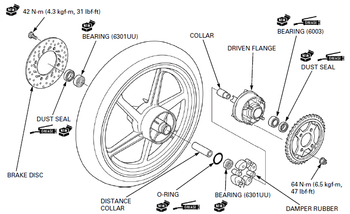
COMPONENT LOCATION
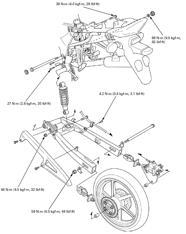
SERVICE INFORMATION
GENERAL
- When servicing the rear wheel and suspension, support the motorcycle using a safety stand or hoist.
- A contaminated brake disc or pad reduces stopping power. Discard contaminated pads and clean a contaminated disc with a high quality brake degreasing agent.
- After the rear wheel installation, check the brake operation by applying the brake pedal.
- Use only tires marked "TUBELESS" and tubeless valves on rim marked "TUBELESS TIRE APPLICABLE".
- Use genuine Honda replacement bolts and nuts for all suspension pivot and mounting point.
SPECIFICATIONS

TORQUE VALUES
Driven sprocket nut 64 N-m (6.5 kgf-m, 47 lbf-ft) U-nut
Rear axle nut 59 N-m (6.0 kgf-m, 44 lbf-ft) U-nut
Rear brake disc bolt 42 N-m (4.3 kgf-m, 31 lbf-ft) ALOC bolt; replace
with a new one.
Shock absorber upper mounting bolt 39 N-m (4.0 kgf-m, 29 lbf-ft)
Shock absorber lower mounting nut 44 N-m (4.5 kgf-m, 32 lbf-ft) U-nut
Swingarm pivot nut 88 N-m (9.0 kgf-m, 65 lbf-ft) U-nut
Drive chain slider screw 5.9 N-m (0.6 kgf-m, 4.4 lbf-ft)
Brake hose guide screw 4.2 N-m (0.4 kgf-m, 3.1 lbf-ft)
Driven sprocket stud bolt 28 N-m (2.9 kgf-m, 21 lbf-ft) Apply locking
agent to the threads.
Step holder mounting bolt 27 N-m (2.8 kgf-m, 20 lbf-ft)
TOOLS

TROUBLESHOOTING
Steers to one side or does not track straight
- Drive chain adjusters not adjusted equally
- Bent axle
- Bent frame
- Worn swingarm pivot components
Rear wheel wobbling
- Bent rim
- Worn wheel bearing
- Worn driven flange bearing
- Faulty tire
- Bent frame or swingarm
- Axle not tightened properly
- Unbalanced tire and wheel
- Insufficient tire pressure
Wheel hard to turn
- Brake drag
- Faulty wheel bearing
- Faulty driven flange bearing
- Bent axle
- Drive chain too tight
Soft suspension
- Weak shock absorber spring
- Oil leakage from damper unit
- Insufficient tire pressure
Stiff suspension
- Bent shock absorber damper rod
- Damaged suspension or swingarm pivot bushing
- Bent swingarm pivot or frame
Rear suspension noisy
- Loose suspension fasteners
- Faulty shock absorber
REAR WHEEL
REMOVAL
Support the motorcycle using a safety stand or hoist, raise the rear wheel off the ground.
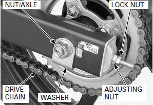
Loosen the lock nut, drive chain adjusting nut and axle nut.
Push the rear wheel forward.
Derail the drive chain from the driven sprocket.
Remove the axle nut.
Do not operate the brake pedal after removing the rear wheel.
Remove the axle and rear wheel.
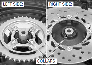
Remove the side collars.
INSPECTION
AXLE
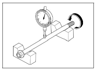
Place the axle on V-blocks.
Turn the axle and measure the runout using a dial indicator.
Actual runout is 1/2 of the total indicator reading.
SERVICE LIMIT: 0.2 mm (0.01 in)
WHEEL RIM
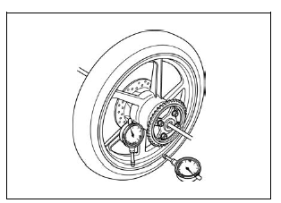
Check the rim runout by placing the wheel in a truing stand.
Spin the wheel by hand, and measure the runout using a dial indicator.
Actual runout is 1/2 of the total indicator reading.
SERVICE LIMITS:
Radial: 2.0 mm (0.08 in)
Axial: 2.0 mm (0.08 in)
WHEEL AND DRIVEN FLANGE BEARINGS
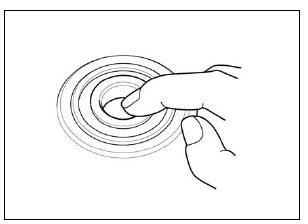
Turn the inner race of each bearing with your finger.
The bearings should turn smoothly and quietly.
Also check that the outer race fits tightly in the wheel hub and driven flange.
Replace the bearings as a set.
Remove and discard the bearings if the races do not turn smoothly, quietly, or if they fit loosely in the wheel hub and driven flange.
WHEEL BALANCE
For wheel balance servicing.
DRIVEN SPROCKET
For driven sprocket inspection.
DISASSEMBLY
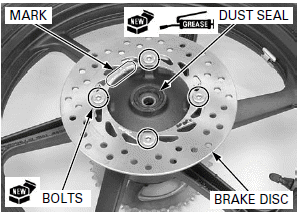
Remove the dust seal from the right wheel hub.
Loosen the brake disc mounting bolts in a crisscross pattern in 2 or 3 steps, and remove the bolts and brake disc.
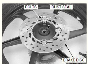
Remove the dust seal from the driven flange.
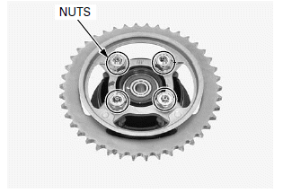
If you will disassemble the driven flange, loosen the driven sprocket nuts in a crisscross pattern in 2 or 3 steps, before removing the driven flange from the left wheel hub.
Remove the driven flange assembly.
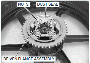
Remove the damper rubbers and O-ring.
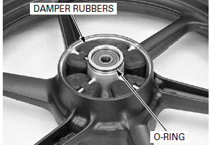
Remove the driven sprocket nuts.
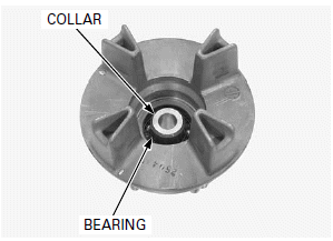
Remove the driven flange collar.
Drive out the driven flange bearing.
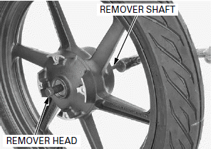
Install the bearing remover head into the bearing.
From the opposite side, install the bearing remover shaft and drive out the bearing from the wheel hub.
Remove the distance collar and drive out the other bearing.
TOOLS:
Bearing remover head, 12 mm 07746-0050300
Bearing remover shaft 07746-0050100
ASSEMBLY
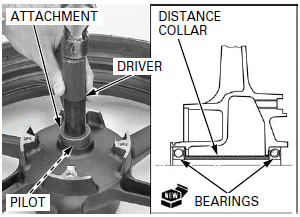
Never install the old bearing, once the bearing has been removed, the bearing must be replaced with new ones.
Drive in a new right side bearing squarely with its marked side facing up until it is fully seated.
Install the distance collar.
Drive in a new left side bearing squarely with its marked side facing up until it is seated on the distance collar.
TOOLS:
Driver 07749-0010000
Attachment, 37 x 40 mm 07746-0010200
Pilot, 12 mm 07746-0040200
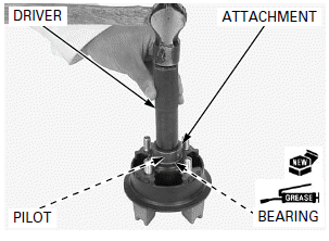
Apply grease to the driven flange bearing rotating area.
Drive in a new driven flange bearing squarely with its sealed side facing up until it is fully seated.
TOOLS:
Driver 07749-0010000
Attachment, 37 x 40 mm 07746-0010200
Pilot, 17 mm 07746-0040400
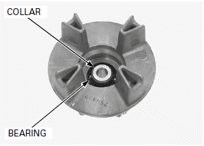
Install the collar to the driven flange bearing.
Install the driven sprocket to the driven flange.
Loosely install the driven sprocket nuts.
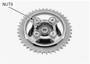
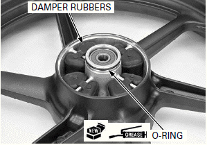
Apply grease to a new O-ring.
Install the O-ring and wheel damper rubbers into the left wheel hub.
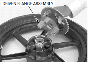
Install the driven flange assembly into the left wheel hub.
Tighten the nuts to the specified torque in a crisscross pattern in 2 or 3 steps.
TORQUE: 64 N-m (6.5 kgf-m, 47 lbf-ft)
Apply grease to a new dust seal lips.
Install the dust seal to the driven flange.
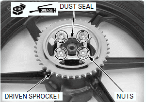
Do not get grease on the brake disc.
Apply grease to a new dust seal lips.
Install the dust seal to the right wheel hub.
Install the brake disc with the stamped mark "MIN.TH. 3.5 mm" facing outside.
Install and tighten new brake disc bolts to the specified torque in a crisscross pattern in 2 or 3 steps.
TORQUE: 42 N-m (4.3 kgf-m, 31 lbf-ft)
INSTALLATION
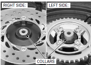
Install the right side collar (short) and left side collar (long).
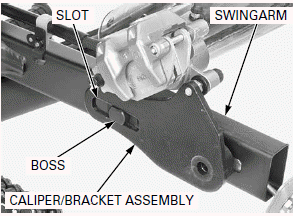
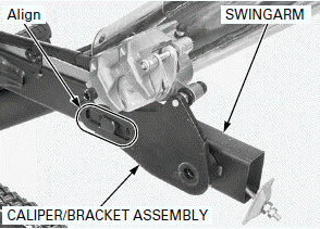
Check the slot of the brake caliper/bracket assembly is installed to the boss of the swingarm.
Be careful not to damage the brake pads.
Install the rear wheel in the swingarm aligning the brake disc between the brake pads.
Install the drive chain over the driven sprocket.
Apply a thin coat of grease to the axle rolling surface.
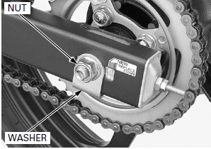
Install the axle from the right side through the axle washer, swingarm, rear wheel and collar.
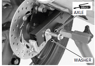
Install the axle washer.
Install and tighten the axle nut to the specified torque.
TORQUE: 59 N-m (6.0 kgf-m, 44 lbf-ft)
Adjust the drive chain slack.
SHOCK ABSORBER
REMOVAL
Support the motorcycle using a safety stand or hoist, raise the rear wheel off the ground.
Remove the rear cowl.
Remove the shock absorber lower mounting bolt and nut.
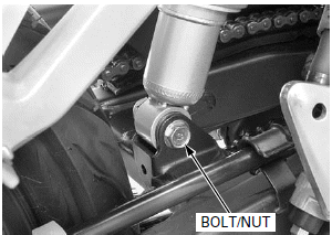
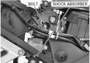
Remove the shock absorber upper mounting bolt and shock absorber.
INSPECTION
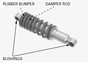
Visually inspect the shock absorber for wear or damage.
Check the following:
- Damper rod for bend or damage
- Damper unit for deformation or oil leaks
- Bushings for wear or damage
- Rubber bumper for wear or damage
Replace the shock absorber as an assembly if necessary.
INSTALLATION
Install the shock absorber and upper mounting bolt.
Tighten the shock absorber upper mounting nut to the specified torque.
TORQUE: 39 N-m (4.0 kgf-m, 29 lbf-ft)
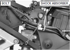
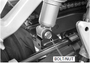
Install the shock absorber lower mounting bolt and nut.
Tighten the lower mounting nut to the specified torque.
TORQUE: 44 N-m (4.5 kgf-m, 32 lbf-ft)
Install the rear cowl.
Check the operation of the shock absorber.
SWINGARM
REMOVAL
Remove the rear wheel.
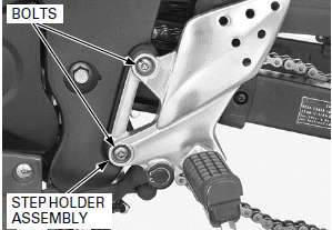
Remove the left step holder mounting bolts and move the left step holder assembly downward.
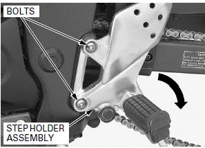
Remove the bolts and chain cover.
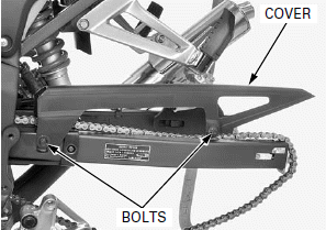
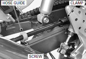
Remove the screw and brake hose guide.
Release the brake hose from the clamp.
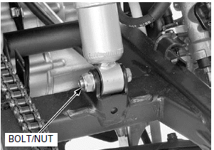
Remove the shock absorber lower mounting bolt and nut.
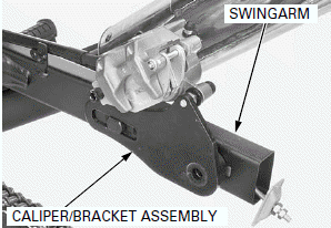
Remove the rear brake caliper/bracket assembly from the swingarm.
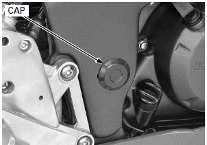
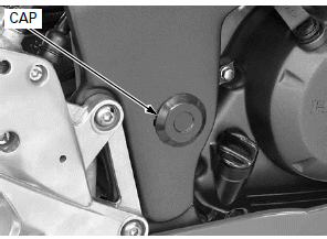
Remove both swingarm pivot caps.
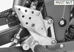
Remove the swingarm pivot nut, pivot bolt and swingarm.
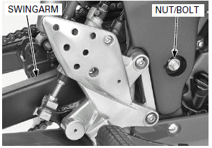
DISASSEMBLY
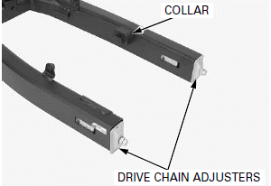
Remove the drive chain adjusters and rubber collar.
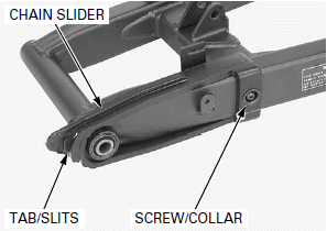
Remove the screw and collar.
Remove the drive chain slider by releasing the slider slits from the swingarm tab.
Check the drive chain slider for wear or damage.
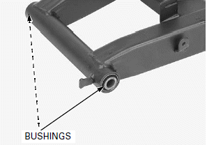
Check the rubber bushings for wear, damage or fatigue and replace if necessary.
ASSEMBLY
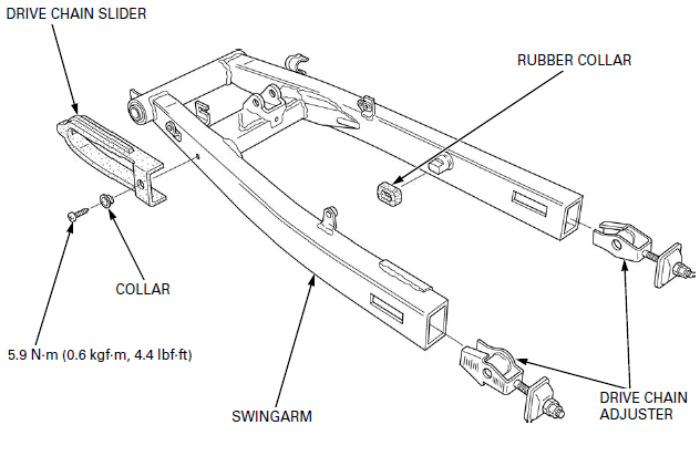
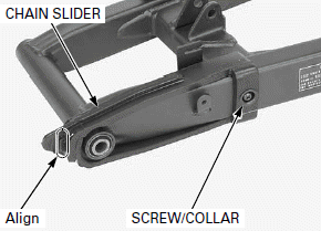
Install the drive chain slider while aligning the swingarm tabs with the slider slits.
Install the collar and drive chain slider screw, then tighten the screw to the specified torque.
TORQUE: 5.9 N-m (0.6 kgf-m, 4.4 lbf-ft)
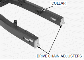
Install the drive chain adjusters and rubber collar.
INSTALLATION
Apply a thin coat of grease to the swingarm pivot bolt sliding surface.
Set the drive chain onto the swingarm and install the swingarm to the frame.
Install the swingarm pivot bolt from the left side.
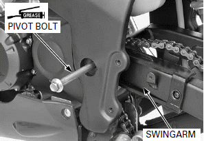
Install the swingarm pivot nut and loosely tighten it.
Install the brake caliper/bracket assembly to the swingarm by aligning the slot of the bracket and boss of the swingarm.
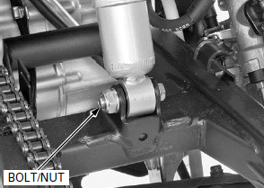
Install the shock absorber lower mounting bolt and nut.
Tighten the lower mounting nut to the specified torque.
TORQUE: 44 N-m (4.5 kgf-m, 32 lbf-ft)
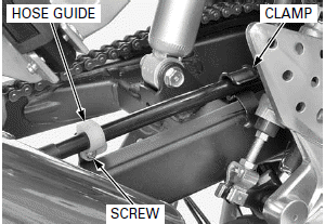
Install the brake hose to the clamp.
Install the brake hose guide and brake hose guide screw, tighten the screw to the specified torque.
TORQUE: 4.2 N-m (0.4 kgf-m, 3.1 lbf-ft)
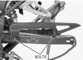
Install the chain cover to the swingarm with aligning the boss of the chain cover with the groove on the swingarm.
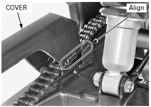
Install and tighten the bolts.
Reposition the left step holder assembly and install the left step holder mounting bolts.
Tighten the mounting bolts to the specified torque.
TORQUE: 27 N-m (2.8 kgf-m, 20 lbf-ft)
Install the rear wheel.
Lift down the motorcycle from the safety stand or hoist, and support the motorcycle by your hands as be preload to the shock absorber and rubber bushings.
Tighten the swingarm pivot nut to the specified torque.
TORQUE: 88 N-m (9.0 kgf-m, 65 lbf-ft)
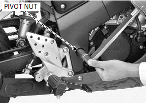
Install both swingarm pivot caps.
Adjust the drive chain slack.
See also:
 Honda CBR125RW - Service manual > Steering Stem
REMOVAL Lift and support the fuel tank. Open the rubber sheet. Disconnect the ignition switch 2P (Natural) connector.
 Honda CBR125RW - Service manual > Hydraulic Brake
COMPONENT LOCATION

 BMW G310GS
 Honda CBR125RW
 Husqvarna 401 Vitpilen
 KTM 890 Duke R
 Mash Dirt Track 650
 Peugeot Kisbee
 Yamaha Tracer MT-09
 Honda CBR125RW
 Peugeot Kisbee
 Yamaha Tracer MT-09