 Honda CBR125RW - Service manual > Spark Plug
REMOVAL
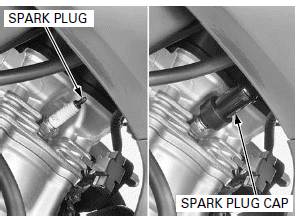
Disconnect the spark plug cap.
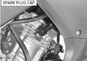
Clean around the spark plug base with compressed air before removing the spark plug, and be sure that no debris is allowed to enter into the combustion chamber.
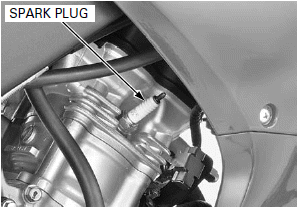
Remove the spark plug using a spark plug wrench.
Inspect or replace the spark plug as described in the maintenance schedule.
INSPECTION
Clean the spark plug electrodes with a wire brush or special plug cleaner.
Check the insulator for cracks or damage, and the electrodes for wear, fouling or discoloration.
Replace the spark plug if necessary.
Always use the specified spark plug on this motorcycle.
RECOMMENDED SPARK PLUG:
Standard:
NGK: CR8E
DENSO: U24ESR-N
Optional:
NGK: CR9E
DENSO: U27ESR-N
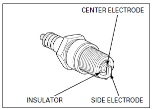
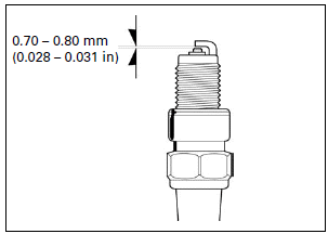
Measure the gap between the center and side electrodes with a feeler gauge.
SPARK PLUG GAP: 0.70 - 0.80 mm (0.028 - 0.031 in)
If necessary, adjust the gap by bending the side electrode carefully.
INSTALLATION
Install and hand tighten the spark plug to the cylinder head, then tighten the spark plug to the specified torque using a spark plug wrench.
TORQUE: 16 N-m (1.6 kgf-m, 12 lbf-ft)
Connect the spark plug cap securely.
VALVE CLEARANCE
INSPECTION
NOTE:
- Inspect and adjust the valve clearance while the engine is cold (below 35ºC/95ºF).
- After the valve clearance inspection, check the engine idle speed.
- Inspect and adjust the valve clearance can be serviced with the engine installed in the frame.
Remove the cylinder head cover.
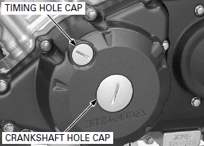
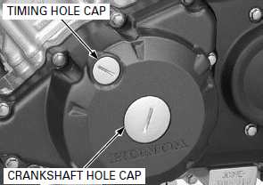
Remove the timing hole cap and crankshaft hole cap.
TOOL: Timing cap wrench 07709-0010001 or equivalent
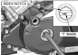
Rotate the crankshaft counterclockwise and align the "T" mark on the flywheel with the index notch on the left crankcase cover.
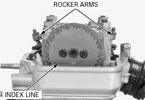
The index line on the cam sprocket must be flush with the cylinder head surface as shown.
Make sure the piston is at TDC (Top Dead Center) on the compression stroke.
This position can be obtained by confirming that there is slack in the rocker arm. If there is no slack, it is because the piston is moving through the exhaust stroke to TDC. Rotate the crankshaft one full turn and match up the "T" mark again.
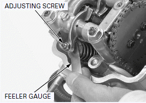
Check the valve clearance by inserting a feeler gauge between the adjusting screw and valve stem.
VALVE CLEARANCE:
IN: 0.06 +- 0.02 mm (0.002 +- 0.001 in)
EX: 0.27 +- 0.02 mm (0.011 +- 0.001 in)
ADJUSTMENT
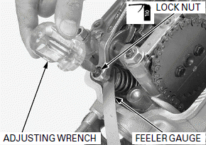
Adjust by loosening the lock nut and turning the adjusting screw until there is slight drag on the feeler gauge.
Apply engine oil to the lock nut threads and seating surface.
Hold the adjusting screw and tighten the lock nut to the specified torque.
TOOLS:
Valve adjusting wrench 07708-0030300
Lock nut wrench 07708-0030100
TORQUE: 10 N-m (1.0 kgf-m, 7 lbf-ft)
Recheck the valve clearances.
Install the cylinder head cover.
Apply engine oil to new O-rings and install them to each hole cap.
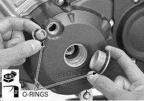
Install and tighten the timing hole cap and crankshaft hole cap to the specified torque.
TORQUE:
Timing hole cap: 6.0 N-m (0.6 kgf-m, 4.4 lbf-ft)
Crankshaft hole cap: 8.0 N-m (0.8 kgf-m, 5.9 lbf-ft)
See also:
 Honda CBR125RW - Service manual > Fuel Line
FUEL TANK LIFTING Remove the following: Single seat Fuel tank cover Remove the bolts. Release the bosses from the grommets of the fuel tank.
 Honda CBR125RW - Service manual > Engine Oil
OIL LEVEL INSPECTION Hold the motorcycle in an upright position. Start the engine and let it idle for 3 - 5 minutes. Stop the engine and wait 2 - 3 minutes.

 BMW G310GS
 Honda CBR125RW
 Husqvarna 401 Vitpilen
 KTM 890 Duke R
 Mash Dirt Track 650
 Peugeot Kisbee
 Yamaha Tracer MT-09
 Honda CBR125RW
 Peugeot Kisbee
 Yamaha Tracer MT-09